Installation structure of knockmeter in internal combustion engine

A technology of knock sensor and installation structure, which is applied in the testing of machine/structural components, engine testing, machine/engine, etc. It can solve problems such as limitation of freedom of installation and configuration, reduction of sensor durability, sensor damage, etc., and achieve improvement Reliability and the effect of preventing malfunction

Inactive Publication Date: 2004-11-03
HONDA MOTOR CO LTD
View PDF3 Cites 11 Cited by
  • Summary
  • Abstract
  • Description
  • Claims
  • Application Information

AI Technical Summary

Problems solved by technology

[0009] The sensor installation structure described in the above-mentioned Patent Documents 1 and 2 is a structure in which a knock sensor is installed on the outer wall portion of the cylinder block (side surface of the cylinder), but the installation position of the sensor is the intake / exhaust side of the internal combustion engine. When the sensor is installed on the exhaust side of the internal combustion engine, the sensor is directly affected by the heat of the exhaust gas, which not only has a bad influence on the detection accuracy of the sensor, but also reduces the durability of the sensor, and sometimes causes the sensor to In order to avoid these problems, it is necessary to use special measures such as the use of heat-resistant sensors that take into account the influence of heat and the installation of heat shields.
[0010] Especially for the internal combustion engine that is installed in a substantially horizontal state on the vehicle body, if the exhaust side is selected as the installation site of the sensor, since the exhaust side is usually located at the lower position of the internal combustion engine, it is considered that the sensor will be in contact with the ground. Direct contact requires protective measures to prevent the sensor from contacting, such as the need for a special protective device for the sensor, so the cost becomes higher
[0011] If the suction side is selected as the installation location, the freedom of installation and arrangement of the auxiliary equipment of the suction system is limited, and problems arise in the optimization of its layout. There are certain restrictions on the order, etc., so there is room for improvement that cannot be improved, such as assemblability.
[0012] In the installation structure of the knock sensor described in the above-mentioned patent documents 1 to 3, the installation position of the knock sensor takes into account the influence of vibration from the auxiliary equipment of the intake system, the auxiliary equipment of the drive system, and from vibration sources such as the timing chain. From the positive point of view of eliminating the influence of this vibration, the selection of the installation position cannot be performed, so the vibration caused by the drive of the auxiliary machinery and the timing chain has a bad influence on the output accuracy of the monitoring signal of the sensor, and damages the sensor. Issues such as sensor output reliability

Method used


Image

  • Installation structure of knockmeter in internal combustion engine
  • Installation structure of knockmeter in internal combustion engine
  • Installation structure of knockmeter in internal combustion engine

Examples


Embodiment Construction

[0029] The following is based on Figure 1 to Figure 6 Embodiments of the present invention will be described.

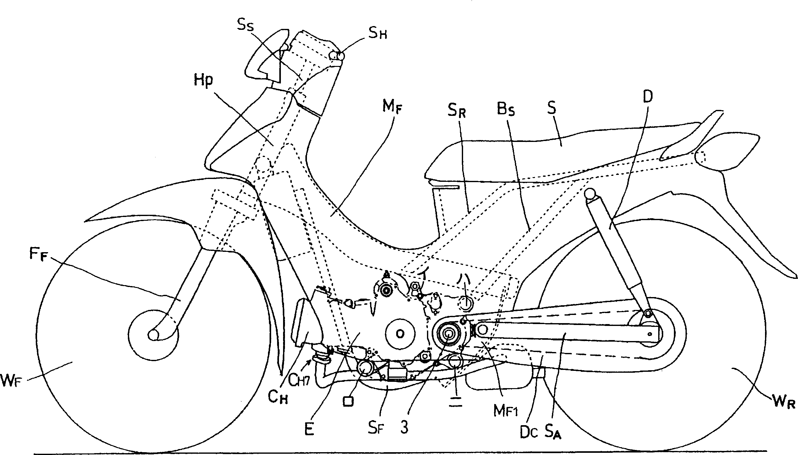
[0030] figure 1 It shows the overall view of the motorized two-wheeled vehicle equipped with the internal combustion engine of the embodiment of the present invention. The motorized two-wheeled vehicle has: the main frame M F ; Front pipe H P , which points slightly towards the main frame M F and installed on its front end; the lower extension of the main frame (internal combustion engine hanger plate) M F1 , which to the main frame M F The lower part of the rear is slightly bent into an arc; the subframe S F , which is connected to the main frame M F The front part of the main frame and the lower extension M of the main frame F1 the lower end of.

[0031] Also available: a pair of seat rails S R , which is mounted on the main frame M F on the bracket set slightly to the middle of the rear, extending to the rear while pointing slightly upward; a pair of r...


PUM


Abstract

To improve detection accuracy in a knock sensor by selecting the sensor mounting position of the cylinder in an internal combustion engine. In a compressor, a boss part CB6 is provided in a side face CB5 of a cylinder, and the knock sensor Ks is mounted on the boss part CB6. The boss part CB6 is placed relatively close to the crankcase C of the cylinder. Furthermore, it is kept off an air intake/exhaust side, and positioned in a side part of the cylinder opposite to the mounting side of a timing chain Tc or a water pump Wp. Thus, the sensor Ks can be mounted at a position apart from the drive source of the chain Tc with positive distances or auxiliaries without any thermal influence such as exhaust gas.

Description

technical field [0001] The present invention relates to an installation structure of a knock sensor for monitoring the knock of an internal combustion engine and outputting the monitoring signal, in particular to an installation structure of the knock sensor for a four-stroke single-cylinder internal combustion engine installed on a vehicle body in a substantially horizontal configuration. Background technique [0002] As the installation structure of existing internal-combustion engine knock sensor, there is installed on the raised portion that embeds the outer surface below the water cooling jacket in the internal-combustion engine with a plurality of cylinders; The knock sensor is installed on the outer wall of the cylinder body through the raised portion provided between them; and the knock sensor is directly installed on the inner diameter wall of the cylinder through the outer wall of the water cooling jacket. These are disclosed in the following patent documents (for ...

Claims


Application Information

Patent Timeline
Patent Type & Authority Applications(China)
IPC IPC(8): F02F1/18F02B77/08F02D35/00F02D45/00G01L23/22G01M15/00
Inventor 菊池一纪久保田良
Owner HONDA MOTOR CO LTD
Why Eureka
Try Eureka