Heat sound refrigerator using noise as driving source

A technology of thermoacoustic refrigerator and driving source, which is applied in refrigerators, refrigeration and liquefaction, lighting and heating equipment, etc., and can solve problems such as consumption

Inactive Publication Date: 2004-12-22
ZHEJIANG UNIV
View PDF0 Cites 13 Cited by
  • Summary
  • Abstract
  • Description
  • Claims
  • Application Information

AI Technical Summary

Problems solved by technology

What they all have in common, however, is the need to expend useful energy for sound work

Method used


Image

  • Heat sound refrigerator using noise as driving source
  • Heat sound refrigerator using noise as driving source

Examples


Embodiment Construction

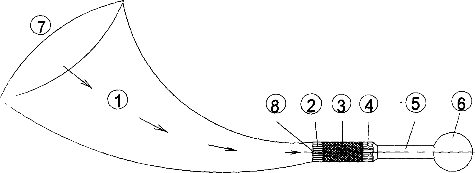
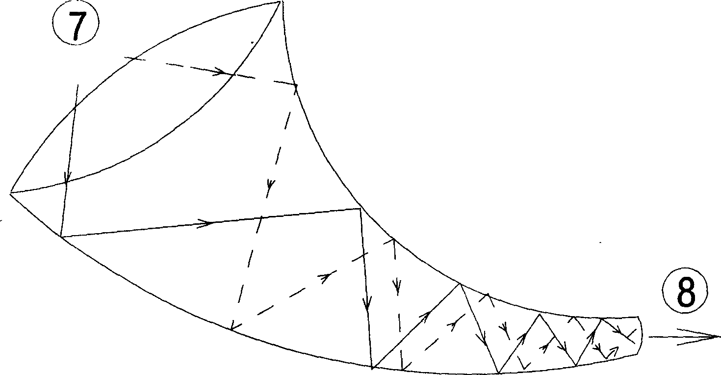
[0008] A thermoacoustic refrigerator with noise as the driving source is connected with a noise collector 1 , a hot-end heat exchanger 2 , a thermoacoustic plate stack 3 , a cold-end heat exchanger 4 , a resonant tube 5 and a resonant cavity 6 . The noise collector 1 is a "horn-shaped" sound channel, and is provided with a noise collector inlet port 7 and a noise collector outlet port 8 .

[0009] The noise collector is the driving source in the system. Although noise is ubiquitous in the environment, its sound pressure level is still too small to be directly exploited by the standards used to drive thermoacoustic refrigerators. In order to achieve the purpose of turning waste into treasure, the first consideration is to increase the sound pressure level. In view of the premise that we do not add new useful energy sources, it is necessary to use a mechanical method to concentrate the sound power of a relatively large area into a relatively small area, so that the sound flow d...


PUM


Abstract

Heat-sound refrigeration machine includes connected noise collector, heat exchanger in heat end, heat-sound plate pile, heat exchanger in cold end, resonating tube and resonant cavity. There are various noise sources including electroacoustic (such as electrodynamic loudspeaker), heat-sound source (such as standing wave type and traveling wave type heat-sound driver) and pneumatic sound source. Consuming available energy is common point of these sound sources (electrical energy, heat energy and kinetic energy). Purpose of the invention is to correct ubiquity noise to drive heat-sound refrigeration machine so as to change wastes into valuables. One directional reflection type oxhorn shaped sound channel is utilized to correct and magnify noise in environment to raise sound pressure level to reach requirement of Heat-sound refrigeration system.

Description

technical field [0001] The invention relates to a thermoacoustic refrigerator with noise as a driving source. Background technique [0002] Thermoacoustic refrigeration is to use the thermoacoustic effect to pump heat, that is, due to the interaction between the solid medium in the sound field and the oscillating fluid, a time-averaged heat flow is generated against the sound propagation direction within a certain range from the solid wall, and in this The phenomenon of absorbing sound work in the area. The thermoacoustic cooling effect obviously relies on the presence of sound waves in the system, so the first job is to generate sound waves. At present, improved dynamic speakers or piezoelectric speakers and high-frequency linear motors are commonly used to drive sound generators. In addition, there are also pneumatic sound wave generators. What they all have in common, however, is the need to expend useful energy for sound work. In the daily env...

Claims


Application Information

Patent Timeline
Patent Type & Authority Applications(China)
IPC IPC(8): F25B23/00
Inventor 金滔陈国邦汤珂
Owner ZHEJIANG UNIV
Why Eureka
Try Eureka