Engine of mixing line wave thermal sound with bypass structure

A thermoacoustic engine and hybrid technology, applied in the direction of machines/engines, mechanical equipment, mechanisms that generate mechanical power, etc., can solve the problems of large loss of sound power and loss

Inactive Publication Date: 2005-01-05
ZHEJIANG UNIV
View PDF0 Cites 7 Cited by
  • Summary
  • Abstract
  • Description
  • Claims
  • Application Information

AI Technical Summary

Problems solved by technology

Using the jet pump structure advocated by Swift et al. of the Los Alamos National Laboratory in the United States, although a better suppression effect can be achieve

Method used


Image

  • Engine of mixing line wave thermal sound with bypass structure
  • Engine of mixing line wave thermal sound with bypass structure
  • Engine of mixing line wave thermal sound with bypass structure

Examples


Embodiment Construction

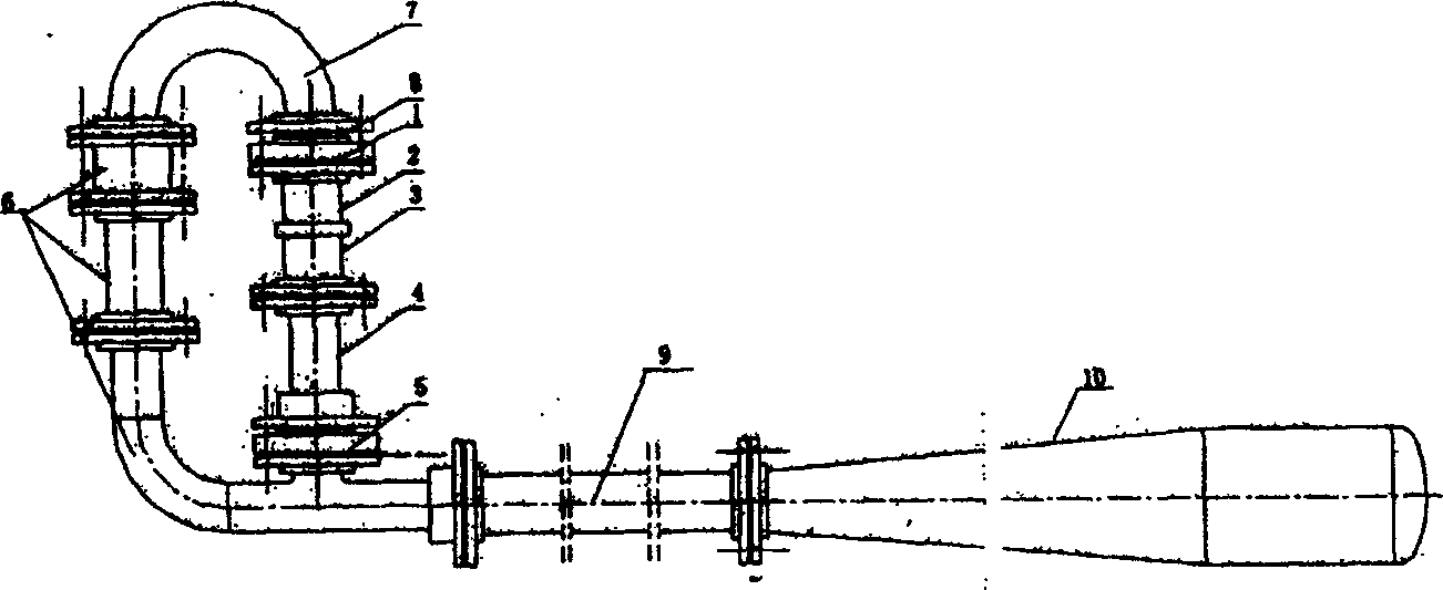
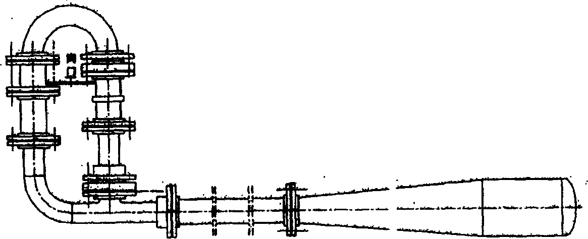
[0027] like figure 2 As shown, a hybrid traveling wave thermoacoustic engine with a bypass structure includes a feedback pipeline 6, a sound capacity pipeline 7, a jet pump 8, a main cooler 1, a thermoacoustic regenerator 2, and a heater 3. Thermal buffer pipe 4, sub-cooler 5, straight resonant path 9, muffler part 10, and a bypass structure is provided between the feedback pipeline 6 and the thermoacoustic regenerator 2. The bypass structure is a bypass pipe, and a valve for adjusting the flow rate of the sound work is arranged on the bypass pipe.

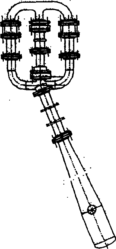
[0028] like image 3 As shown, another hybrid traveling wave thermoacoustic engine with a bypass structure includes a feedback pipeline 6, a sound volume pipeline 7, a jet pump 8, a main cooler 1, a thermoacoustic regenerator 2, a heating 3, heat buffer pipe 4, sub-cooler 5, straight resonant path 9, muffler part 10, and a second feedback line is connected to the entrance of the sound capacity pipeline 7 and the straight resona...


PUM


Abstract

The invention discloses a compound traveling wave thermo-acoustic motor with by-pass structure. It includes feedback channel, acoustic capacitance channel, ejector pump, a primary cooler, thermal acoustic regenerator, heater, thermal buffer channel, a supplementary cooler, a resonance straight-path, muffling part. The by-pass structure is arranged between the feedback channel and the thermal acoustic regenerator. The invention provides a by-pass structure used in the compound traveling wave thermal acoustic motor in order to the reduce the acoustic power loss in the traveling wave loop and restrain the direct current in the loop. Thus the performance of the motor can be improved greatly.

Description

technical field [0001] The invention relates to a hybrid traveling wave thermoacoustic engine with a bypass structure, and the bypass structure can improve the performance of the thermoacoustic engine. Background technique [0002] A thermoacoustic engine is a sound wave generator that uses the thermoacoustic effect to convert heat energy into sound energy and achieve sound power output. According to different sound field characteristics, thermoacoustic engines are mainly divided into three types: standing wave type, traveling wave type and standing wave traveling wave hybrid type. Since the phase difference between the velocity wave and the pressure wave in the standing wave acoustic field is 90°, theoretically there is no work transmission in the standing wave field; It is an irreversible thermodynamic cycle, so the efficiency of the thermoacoustic engine is low. The traveling wave thermoacoustic engine utilizes the traveling wave sound field, the phase of the velocity f...

Claims


Application Information

Patent Timeline
IPC IPC(8): F03G7/00
Inventor 邱利民孙大明严伟林陈萍甘智华陈国邦
Owner ZHEJIANG UNIV
Why Eureka
Try Eureka