Multifunctional optical quality detector

A technology of optical quality and detection devices, which is applied in the field of optical components, can solve problems such as the inability to measure local errors of components, the inability to detect error information, and the difficulty in obtaining error information, etc., to achieve short measurement time, low manufacturing accuracy, and low manufacturing accuracy requirements Effect

Inactive Publication Date: 2005-01-12
SHANGHAI INST OF OPTICS & FINE MECHANICS CHINESE ACAD OF SCI
View PDF0 Cites 9 Cited by
  • Summary
  • Abstract
  • Description
  • Claims
  • Application Information

AI Technical Summary

Problems solved by technology

[0005] 2. Unable to measure local error of components
The measured error is only the surface error of different annular zones of the tested component, and the error information of each local small area of ​​the component is difficult to obtain
[0006] 3. Sampling density is limited
The distance between the small holes on the diaphragm is fixed, and the sampling can only be done at a certain density, so that the error information of the ring zone area corresponding to the space between the small holes on the diaphragm cannot be detected, resulting in low measurement accuracy
[0007] 4. Long measurement time
The traditional method usually adopts the photographic method. In the measurement process, a series of steps such as film exposure, development, and spot position measurement are required, which takes a long time. At the same time, random factors such as vibration may be introduced during the process, which will cause great Measurement error

Method used


Image

  • Multifunctional optical quality detector
  • Multifunctional optical quality detector
  • Multifunctional optical quality detector

Examples


Embodiment Construction

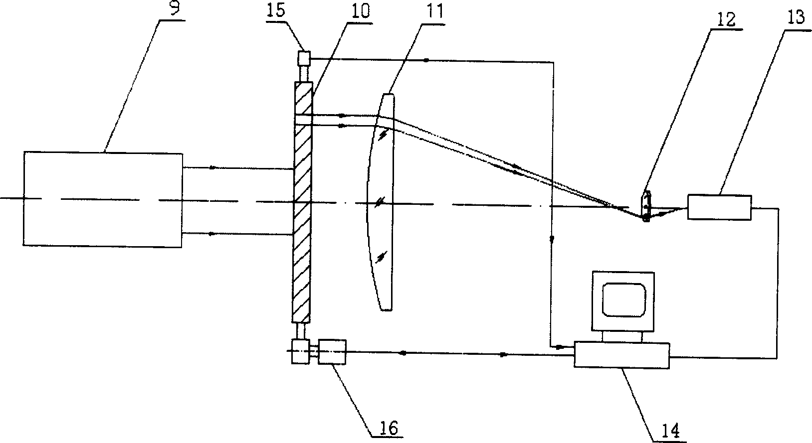
[0028] see image 3 , image 3 It is a structural schematic diagram of an embodiment of the multifunctional optical quality detection and analysis device of the present invention. As can be seen from the figure, the multifunctional optical quality detection device of the present invention is composed of a standard collimator 9, a scanning Hartmann diaphragm 10, a focused lens 11 to be inspected, and a microscope objective lens 12 on a common optical axis. , CCD camera 13, described scanning Hartmann diaphragm 10 is installed on the diaphragm support, and this support top is fixed with encoder 15, and stepper motor 16 is housed below, also has computer 14, and described CCD camera 13 is positioned at the focus position of microscope objective lens 12, and described CCD camera 13, encoder 15 and stepper motor 16 are all connected with computer 14; Under the control of computer 14, drive scanning type Hartmann aperture by stepper motor 16 10 rotates around the optical axis. On ...


PUM


Abstract

The testing device includes standard collimator, scan type Hartmann diaphragm, focusing mirror, and CCD camera. The Hartmann diaphragm is installed on diaphragm bracket. Encoder is fixed on upper part of the bracket, and step motor and computer are installed on lower part of the bracket. Under control of computer, step motor drives scan type Hartmann diaphragm to rotate around optical axis, and computer receives image output from CCD camera and position information of scan type Hartmann diaphragm from encoder, and carries out data process for image. The invention can be applied for guiding fabricating optical elements, adjustment of optical path, evaluating qualities of incident beam and focal spot, possessing advantages of high testing precision, quick speed, and multiple functions.

Description

Technical field: [0001] The invention relates to an optical element, in particular to a multifunctional optical quality detection device. Background technique: [0002] In the prior art, the structure of the traditional Hartmann inspection device is as follows: figure 1 As shown, the light emitted by the light source 1 illuminates the aperture diaphragm 3 through the condenser lens 2, thereby obtaining a point light source; 4 After being collimated into a parallel beam, it is irradiated on the Hartmann diaphragm 5, and the parallel beam is divided into many pairs of thin beams with different heights, and then directed to the tested component 6. The distance between the center of the thin beam and the optical axis is measured at positions 7 and 8 by means of photography, and the aberration information is obtained through analysis. The structure of the Hartmann aperture 5 is as follows figure 2 As shown, the small hole pairs on the Hartmann diaphragm 5 are distributed symm...

Claims


Application Information

Patent Timeline
Patent Type & Authority Applications(China)
IPC IPC(8): G01N21/00
Inventor 黄惠杰刘丹任冰强赵永凯阎岩王向朝张维新王树森
Owner SHANGHAI INST OF OPTICS & FINE MECHANICS CHINESE ACAD OF SCI
Why Eureka
Try Eureka