Method and device for heat treatment

A heat treatment method and technology of a heat treatment device, which are applied in furnace control devices, lighting and heating equipment, furnaces, etc., can solve the problems of difficult heat treatment and increased operating costs, and achieve the effect of reducing operating costs.

Inactive Publication Date: 2005-01-12
TOKYO ELECTRON LTD
View PDF0 Cites 4 Cited by
  • Summary
  • Abstract
  • Description
  • Claims
  • Application Information

AI Technical Summary

Problems solved by technology

[0007] Usually, the dummy semiconductor wafer used to replenish the empty processed object holding portion in the product wafer mounting area is made of the same material as the semiconductor wafer to be processed, for example, silicon, although it may be used in multiple processes. Washing is performed every time and used repeatedly, but because it is finally disposed of, it becomes a cause of increased running costs, and therefore, there is a problem that it is difficult to effectively perform predetermined heat treatment

Method used


Image

  • Method and device for heat treatment
  • Method and device for heat treatment
  • Method and device for heat treatment

Examples


no. 1 approach

[0050] Hereinafter, the present invention will be described by taking, as an example, a vertical heat treatment apparatus that performs film formation treatment on an object to be processed by heat treatment such as CVD, while referring to the drawings.

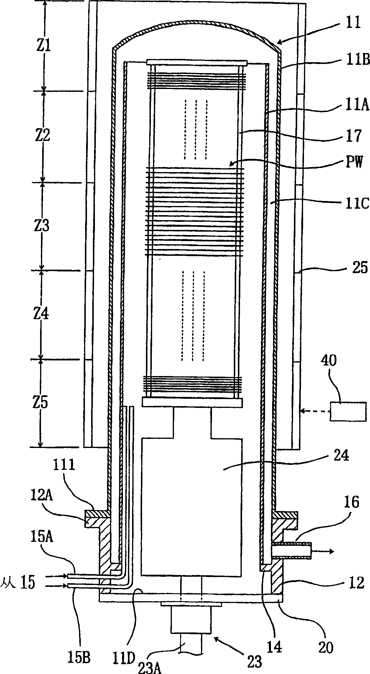
[0051] figure 1 It is an explanatory sectional view showing a schematic configuration of an example of the vertical heat treatment apparatus of the present invention.

[0052] In this vertical heat treatment apparatus, there is provided a reaction vessel (processing pipe) 11 having figure 1 11A, a straight inner tube 11A arranged to extend upwards and to have an open upper end, and an outer tube 11B, which is concentrically arranged at predetermined intervals and has a closed upper end so as to form a cylindrical space 11C around the inner tube 11A. With the double-pipe structure, the space below the reaction container 11 is a loading area for transferring semiconductor wafers PW and the like of the target object to the wafe...

experiment example 1

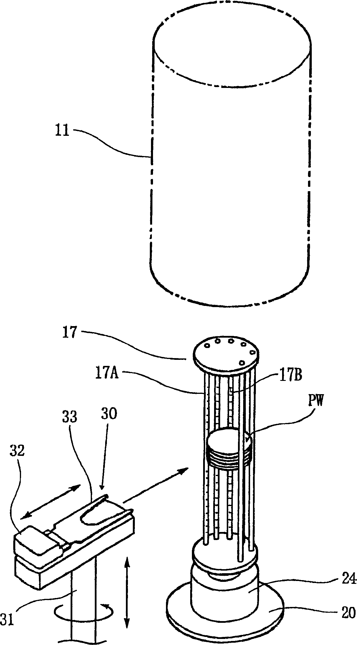
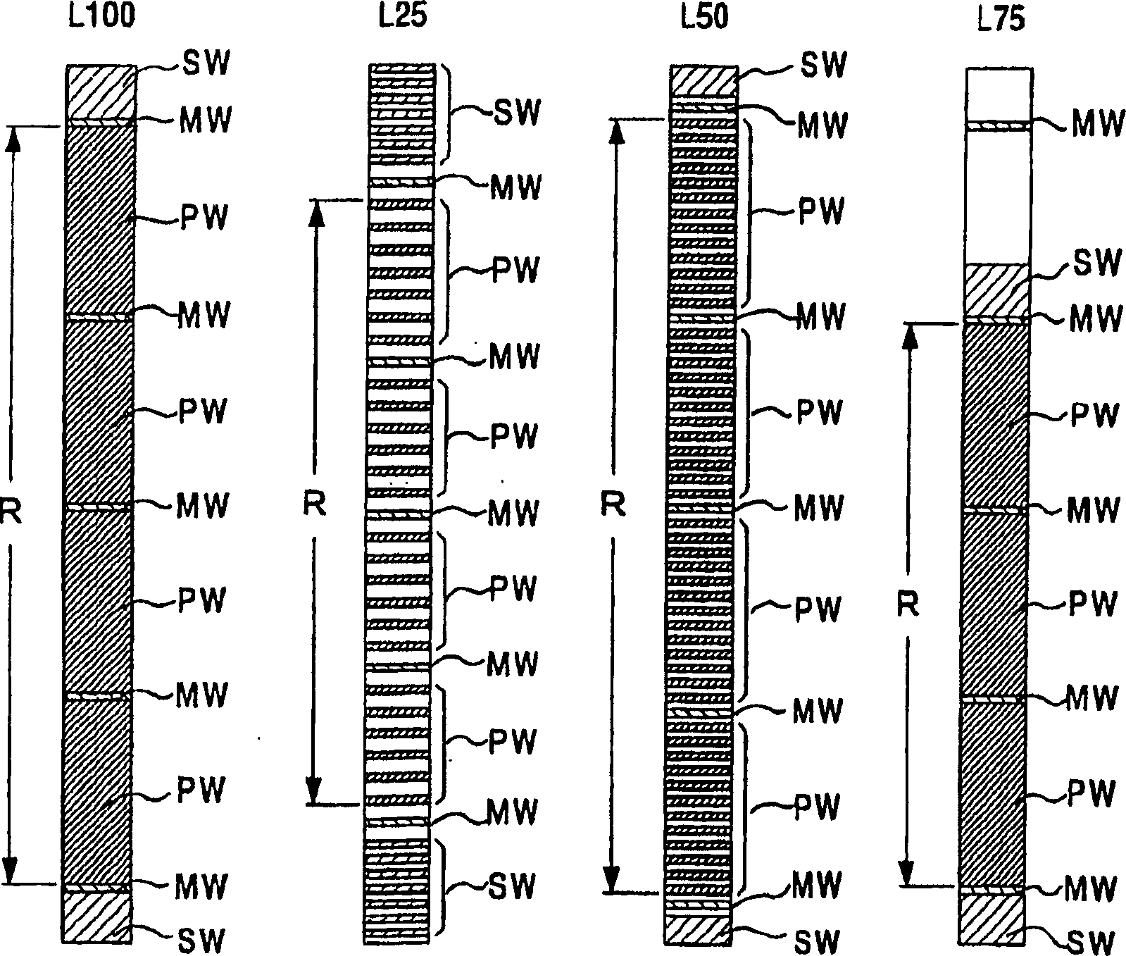
[0105] Using the wafer boat 17 capable of carrying 100 product wafers, according to image 3 In the shown reference loading pattern L25, 20 product wafers PW are sequentially loaded from the object-to-be-processed holding part located below the product wafer loading area R, and 20 product wafers PW are placed in the five empty positions where product wafers are to be cut. A dummy wafer is placed on the handle holder. In this state, the wafer boat 17 is carried into the reaction vessel 11, and the target heating temperature (processing temperature) of the product wafer is set at 760° C. under the processing conditions corresponding to the reference loading mode L25. Film formation process of silicon nitride film (SiN film) of target value. In this case, each product wafer PW can be formed into a film within a range in which the uniformity of the film thickness in the plane (in-plane uniformity) is within the range of ±1.0% and located below the slave wafer boat 17. Start the ...

no. 2 Embodiment approach

[0110] Hereinafter, an embodiment of the vertical heat treatment apparatus of the present invention will be described by taking an apparatus for film formation as an example. Figure 5 and Image 6 shows the overall appearance of the vertical heat treatment apparatus of this embodiment, in Figure 5 Among them, 120 is a casing forming the exterior part of the apparatus, 121 is a carrier conveying part, 122 is a carrier conveying mechanism, 123 is a carrier stocker, and 124 is a transfer platform, which is configured to store semiconductor wafers ( Hereinafter referred to as wafer) W (in Figure 5 The carrier C is carried into the transport unit 121 , temporarily stored in, for example, the carrier stocker 123 by the carrier transport mechanism 122 , and then transported to the delivery station 124 . In addition, 103 in the figure is a wafer transfer mechanism 103 forming a transfer mechanism provided in the wafer loading chamber 125, which will be described in detail later. ...


PUM


Abstract

A thermal processing method selects a batch size range including the number of workpieces to be processed from a plurality of batch size ranges including batch size ranges in which reference numbers smaller than the holding capacity of a workpiece holder are maximums. The workpieces are distributed in the workpiece holder on the basis of the workpiece distribution pattern determined corresponding to the specified batch size range. Processing conditions of the thermal process are determined according to the workpiece distribution pattern. A thermal processing apparatus comprises a controller capable of carrying out the thermal processing method.

Description

technical field [0001] The present invention relates to a heat treatment method and a heat treatment apparatus. Specifically, the present invention relates to a heat treatment method and a heat treatment apparatus implemented in a batch type heat treatment apparatus for simultaneously performing heat treatment on a plurality of objects to be processed. Background technique [0002] In the manufacturing process of semiconductor devices, various heat treatment apparatuses are used in order to perform heat treatment such as oxidation, diffusion, and film formation on an object to be processed such as a semiconductor wafer, and for example, a plurality of objects to be processed can be simultaneously performed. A batch-type vertical heat treatment apparatus for heat treatment is known. [0003] In such a vertical heat treatment apparatus, a wafer boat serving as an object-to-be-processed holder holding a plurality of semiconductor wafers is stored in a reaction vessel in a horiz...

Claims


Application Information

Patent Timeline
Patent Type & Authority Applications(China)
IPC IPC(8): F27D19/00H01L21/00
CPCH01L21/67253H01L21/67109H01L21/67098F27D19/00H01L21/324
Inventor 坂本浩一竹永裕一横田隆川村和广
Owner TOKYO ELECTRON LTD
Why Eureka
Try Eureka