Coating applied antenna and method of making same

An antenna and coating technology, which is applied in the field of coated antenna and its manufacture, can solve the problems of inapplicability, etc.

Inactive Publication Date: 2005-01-19
유니테크유한책임회사
View PDF4 Cites 5 Cited by
  • Summary
  • Abstract
  • Description
  • Claims
  • Application Information

AI Technical Summary

Problems solved by technology

However, conventional flat PC board technology cannot be applied to steep hyperbolic aircraft surfaces, such as aircraft wings, aircraft fuselage, etc.

Method used


Image

  • Coating applied antenna and method of making same
  • Coating applied antenna and method of making same
  • Coating applied antenna and method of making same

Examples


Embodiment Construction

[0027] In describing the preferred embodiment of the invention illustrated in the drawings, specific terminology will be used for the sake of clarity. However, it is not intended that the invention be limited to the specific terms so selected, and it is to be understood that each specific element includes all technical equivalents which operate in a similar manner to accomplish a similar purpose.

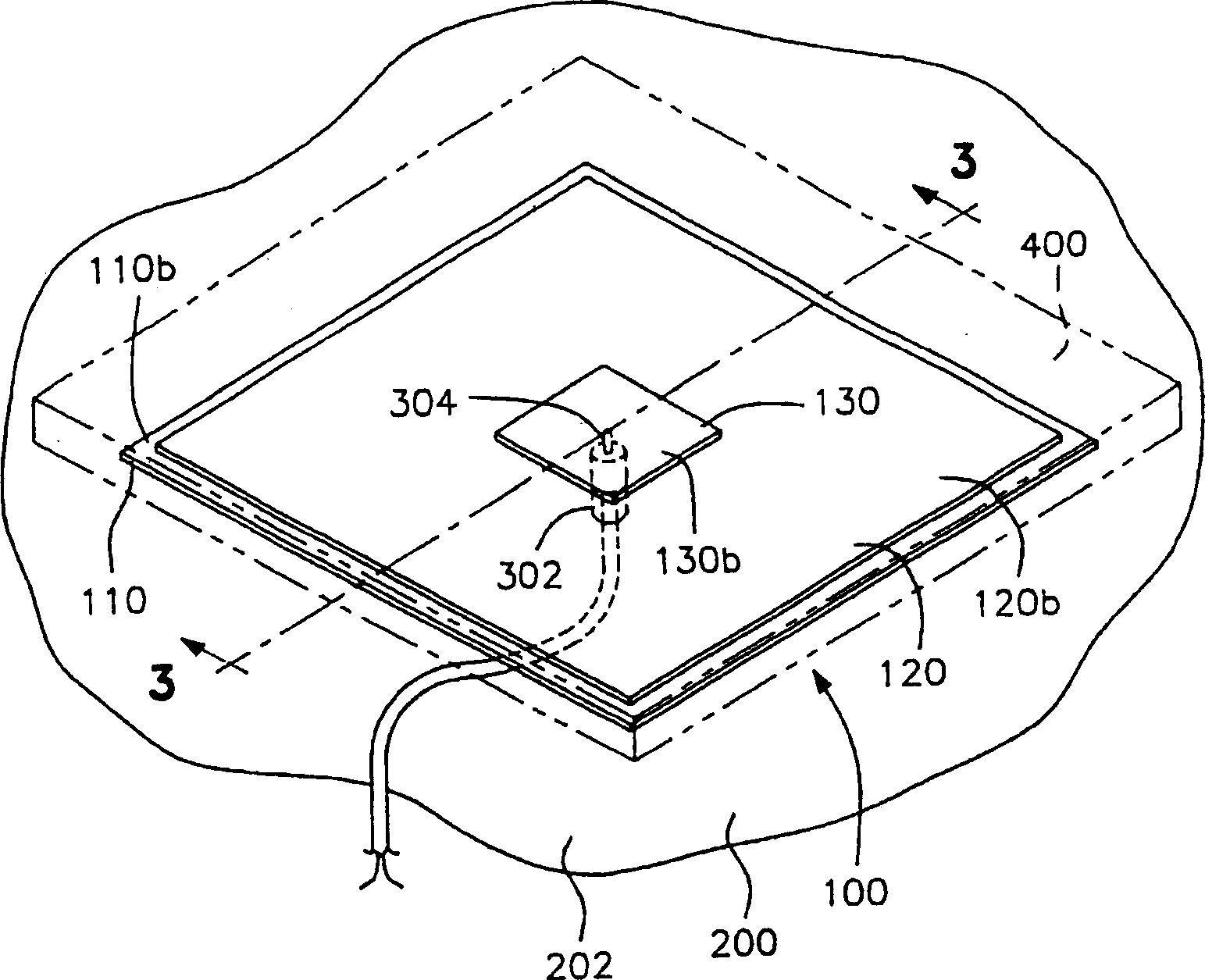
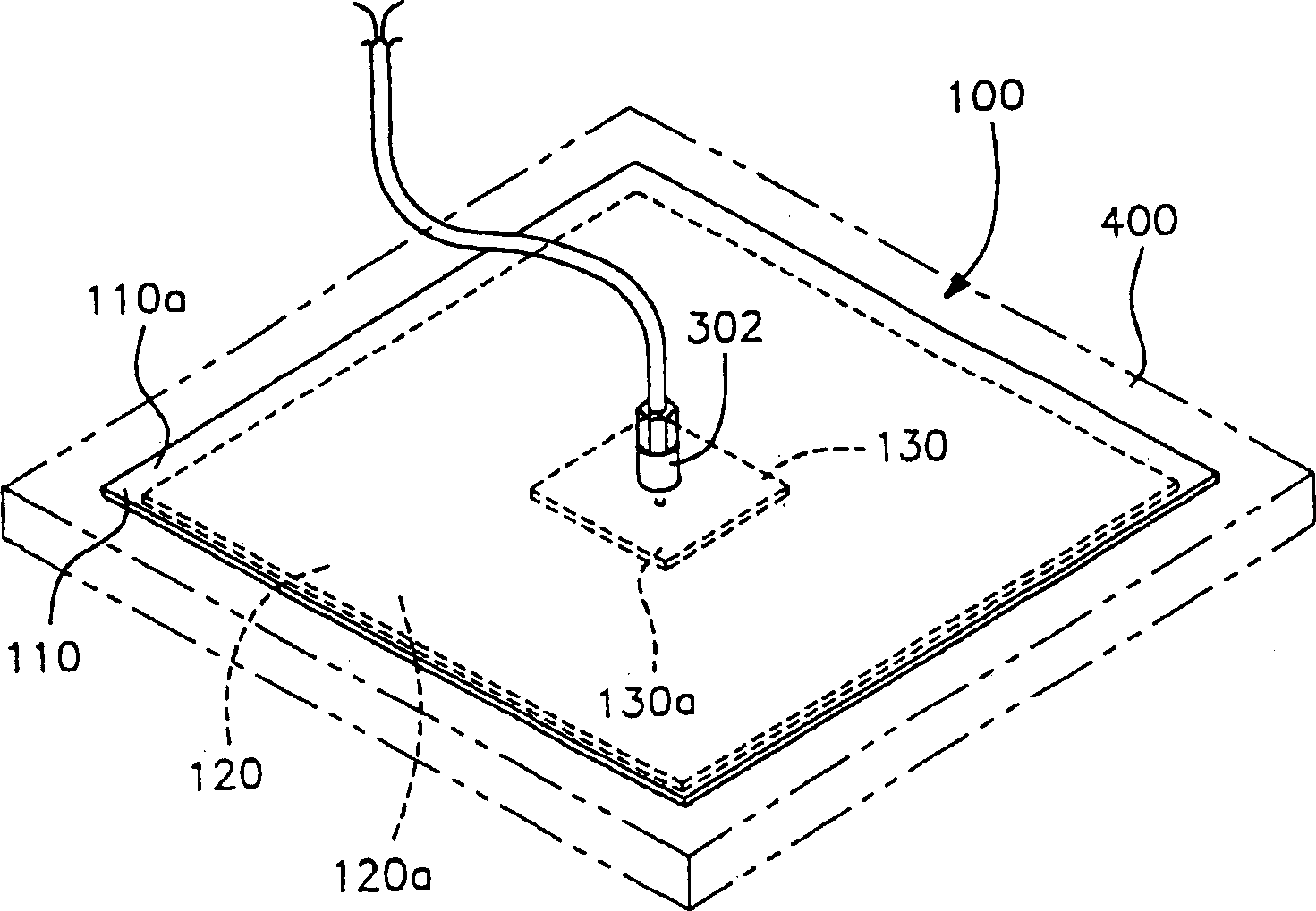
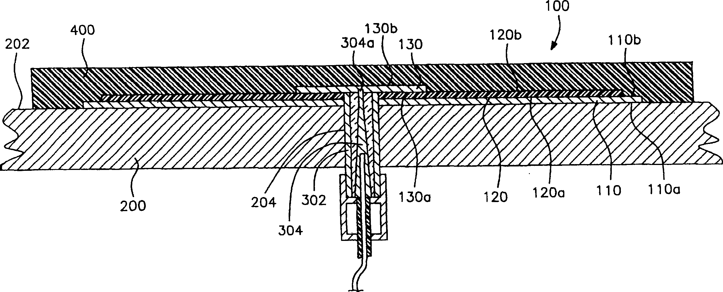
[0028] Now refer to the attached Figure 1-3 , which represents the antenna 100 of the present invention added to the outer surface of a substrate structure 200, such as a curved aircraft surface, especially a steep or hyperbolic surface, such as an aircraft wing, fuselage, etc., and internal communication System benches, such as ships, aircraft, building structures, etc. The material from which the substrate structure 200 is made can be, for example, aluminum, steel, metal alloys, composite structures, fiber reinforced plastics, polycarbonate, acrylic, polyethylene, polypropylene,...


PUM


Abstract

An antenna 100 applied to a structure 200, the antenna 100 comprising a series of conductive and dielectric coatings. A conductive coating backplane or ground plane 110 is applied to a substrate structure 200, a non-conductive dielectric coating 120 is applied over the outer surface of the conductive coating backplane or ground plane 202, and a conductive coating patch, microstrip array or radiating element 130 is applied over the outer surface of the dielectric coating 120b. The pin of a coaxial cable 304 extends through the conductive coating backplane 110, the dielectric coating 120, and the conductive coating patch 130, for transmission of a signal from the antenna 100. The method allows for the non-destructive application of antennas on existing platforms for receiving and transmitting electromagnetic signals.

Description

[0001] This application claims priority to US Patent Application Serial No. 60 / 330679, filed October 29,2001. technical field [0002] This invention relates to coated antennas and methods of making the same. More particularly, the present invention relates to a coated antenna which utilizes a conductive coating to replace the metal portions of conventional antennas and a dielectric coating to replace the dielectric layers of conventional antennas. Background technique [0003] The military requires small form factor, low cost, low maintenance antennas that can be flush mounted on various types of land, air and water rigs including (but not limited to) tanks, aircraft, In boats, and even in cloth items. The aerospace industry now offers mechanically scanned phased arrays in small form factors. Small form factor mechanically scanned antennas are also now available that provide wider scan coverage at very low cost. Both phased array and mechanical antennas are suitable for ...

Claims


Application Information

Patent Timeline
Patent Type & Authority Applications(China)
IPC IPC(8): H01Q1/28H01Q1/38H01Q1/40H01Q9/04
CPCH01Q9/045H01Q1/38Y10T428/254H01Q1/28H01Q1/40H01Q9/0407
Inventor 罗伯特·C·博伊德韦恩·B·莱格兰德
Owner 유니테크유한책임회사
Why Eureka
Try Eureka