
Sealed electric elements

An electrical component, sealing technology, applied in the direction of electrical components, resistor components, circuits, etc., can solve the problem that the sealing resin cannot be fully bonded to the inner peripheral surface of the box, the sealing resin cannot be bonded, and the airtightness is damaged. issues of sex

Inactive Publication Date: 2005-02-02
ALPS ALPINE CO LTD
View PDF1 Cites 3 Cited by
  • Summary
  • Abstract
  • Description
  • Claims
  • Application Information

AI Technical Summary

Problems solved by technology

[0007] However, in the structure of the above-mentioned conventional sealed electrical component, as the size of the product decreases, the bonding area between the inner peripheral surface of the case and the sealing resin (resin adhesive) decreases. When the thermal (linear) expansion coefficient is larger than the thermal (linear) expansion coefficient of the box body, when the temperature is low, the radial shrinkage of the sealing resin is larger than the shrinkage of the circumference of the box body, so that there will be problems in which the sealing resin and the inner diameter of the box cannot be realized. The inner peripheral surface of the box is fully bonded, which will damage the airtightness
[0008] In addition, when the thermal (linear) expansion coefficient of the sealing resin (resin adhesive) and the cover is smaller than the thermal expansion coefficient of the cover, when the temperature is high, the change in the inner circumference of the case is larger than the radial expansion of the sealing resin. It must be large, so there will be a problem that the sealing resin cannot be fully bonded to the inner peripheral surface of the box, and the airtightness will be impaired.

Method used


Image

  • Sealed electric elements
  • Sealed electric elements
  • Sealed electric elements

Examples


Embodiment Construction

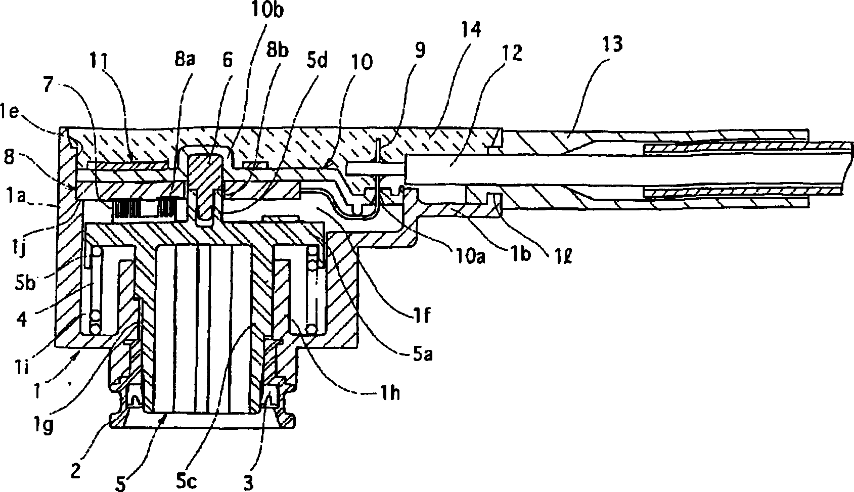
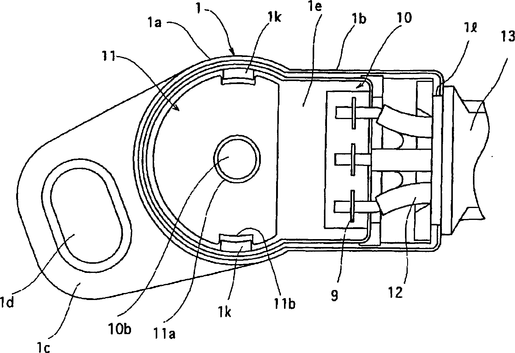
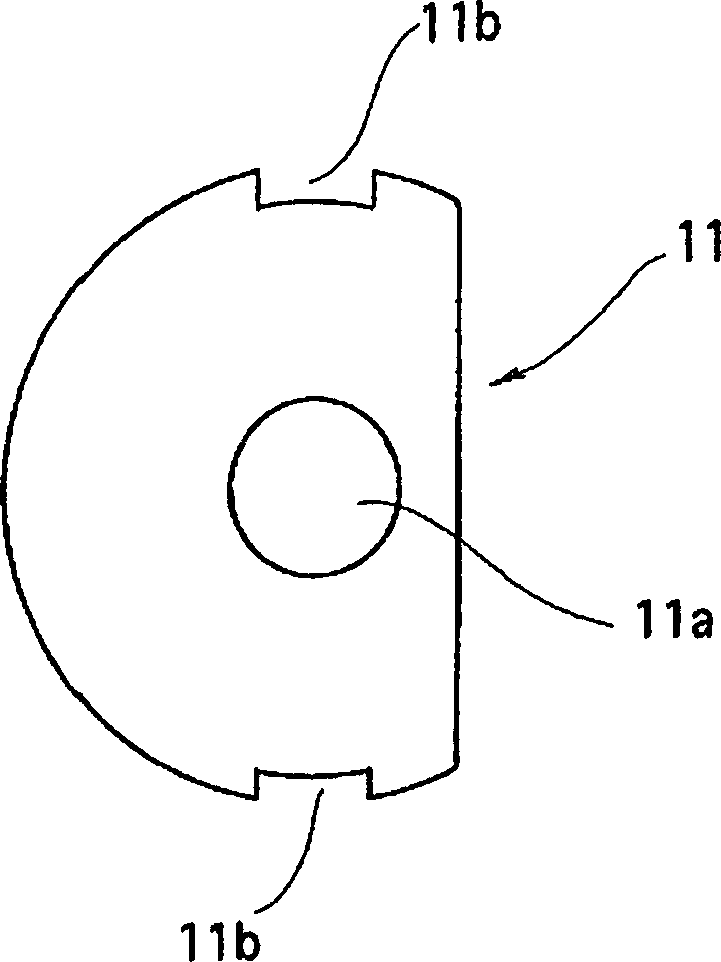
[0018] Figure 1 to Figure 3 An example of the present invention is shown. figure 1 is a cross-sectional view of the sealed electrical component of the present invention, figure 2 is a top view of a sealed electrical component, image 3 It is a plan view of the separator of the sealed electrical part.

[0019] In the figure, the box body 1 is formed of an insulating material such as synthetic resin into a box shape with an open top, and is formed by a substantially cylindrical base 1a and a substantially rectangular platform 1b protruding from one side of the base 1a. Moreover, on the other side surface of the base part 1a, the mounting plate 1c of a substantially table shape is extended toward the direction opposite to the table part 1b. An elliptical screw hole 1d is provided in the mounting plate 1c, and external screws are inserted into the screw hole to be mounted on a chassis or the like. In addition, a continuous opening 1e is provided on the top side of the base ...


PUM


Abstract

The invention provides a seal electrical part, comprising a box body, a base plate, a cover body and adhesives, wherein, an opening is arranged on the box body; an external terminal extending toward the opening is arranged on the base plate; the cover body is embedded in the inner peripheral surface of the opening and is provided with a through hole for the external terminal to pass through; the adhesives is filled on the upper surface of the cover body to seal the inner peripheral surface of the opening and the embedded part of the cover body as well as the external terminal and the embedding part of the cover body; a plate-like partition is buried in the resin of the adhesives along the surface of the cover body; the partition is made of sheet materials; the physical parameter of the partition is between the coefficient of linear expansion of the box body and the adhesives, and is much closer to the coefficient of linear expansion of the box body. The seal electrical part has the advantage that the seal electrical part is not affected by the materials of the cover body even if the thermal expansion coefficients of the resin adhesives and the cover body are different; therefore, the gap is hard to be generated between the resin adhesives and the cover body and the tight contact is realized between the resin adhesives and the inner periphery of the box body, and the air tightness is enhanced.

Description

technical field [0001] The present invention relates to electrical components, and particularly relates to the structure of a sealed electrical component such as a throttle opening sensor mounted on an automobile or the like. Background technique [0002] The structure of conventional sealed electrical components is that a rotor having a brush is rotatably held in a housing portion of a case having a housing portion opened on the upper surface, and an insulating substrate having a resistor body in sliding contact with the brush, and a cover The cover of the insulating substrate is mounted on the opening of the housing, and the terminals drawn from the insulating substrate are protruded from the cover, soldered to the wires, and the opening is filled and sealed with a sealing resin (for example, see Patent Document 1). [0003] Next, the structure of a conventional sealed electrical component will be described with reference to the drawings. Figure 4 It is a sectional view s...

Claims


Application Information

Patent Timeline
IPC IPC(8): H01C10/32H01C1/024H01C10/00H01R9/16
Inventor 阿部英树菊池信士
Owner ALPS ALPINE CO LTD
Learn More