High frequency receiving device, integrated circuit used for same, and TV receiver using them
一种接收装置、高频的技术,应用在用单独的预调谐电路进行不连续调谐、电视、仅具有可变电感/电容的单谐振电路等方向,能够解决不能振荡等问题
- Summary
- Abstract
- Description
- Claims
- Application Information
AI Technical Summary
Problems solved by technology
Method used
Image

Examples
no. 1 approach
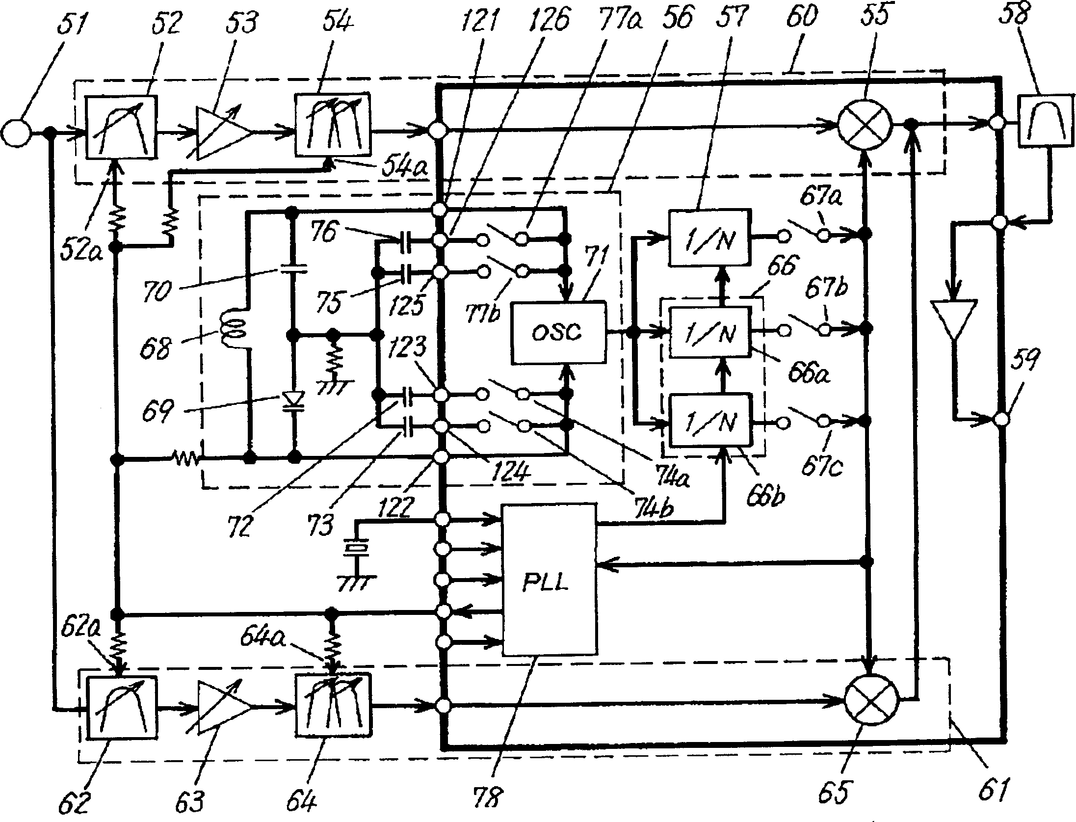
[0035] Hereinafter, a first embodiment of the present invention will be described using the drawings. figure 1 It is a block diagram of the high-frequency receiving device of the first embodiment.
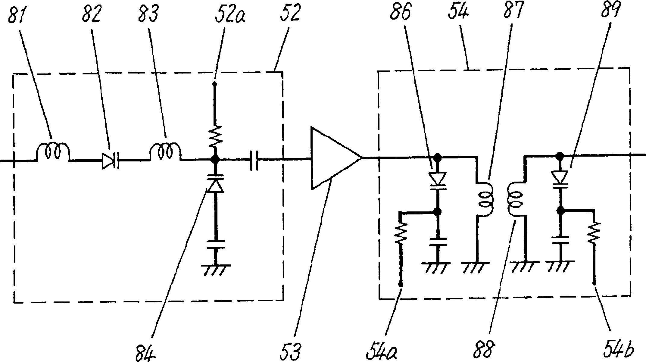
[0036] exist figure 1 , a high-frequency signal from 55.25 MHz to 801.25 MHz is input to the input terminal 51 . This high-frequency signal is supplied to a monotuned filter 52 . The single-tuned filter 52 is a single-tuned filter including one variable-capacitance diode, and its tuning frequency can be changed by a tuning voltage supplied to a variable-frequency terminal 52a. The tuning frequency of the single tuned filter 52 is between the UHF broadcast band from 367.25 MHz to 801.25 MHz.
[0037]The output of the monotuned filter 52 is connected to a high frequency amplifier 53 which amplifies the signal of the UHF broadcast band. The output of the high-frequency amplifier 53 is connected to a multituned filter 54 . This multi-tuning filter 54 includes two variable capaci...
no. 2 approach
[0093]The second embodiment is characterized in that reception of the UHF broadcast band and reception of the VHF broadcast band are performed with only one mixer. Therefore, it contributes to miniaturization and price reduction. Hereinafter, a second embodiment will be described. In addition, the same code|symbol is attached|subjected to the same part as 1st Embodiment, and description is simplified.
[0094] Figure 5 It is a block diagram of the high-frequency receiving apparatus of the second embodiment. exist Figure 5 , the broadcast waves of the UHF broadcast band and the VHF broadcast band are input to the input terminal 132 . Moreover, on this input terminal 132, in order to pass the UHF broadcast frequency band, it is connected in parallel with the first serially connected body of the single-tuned filter 52, the high-frequency amplifier 53, and the multi-tuned filter 54, in order to pass the VHF broadcast frequency band. It is connected in parallel with the seco...
no. 3 approach
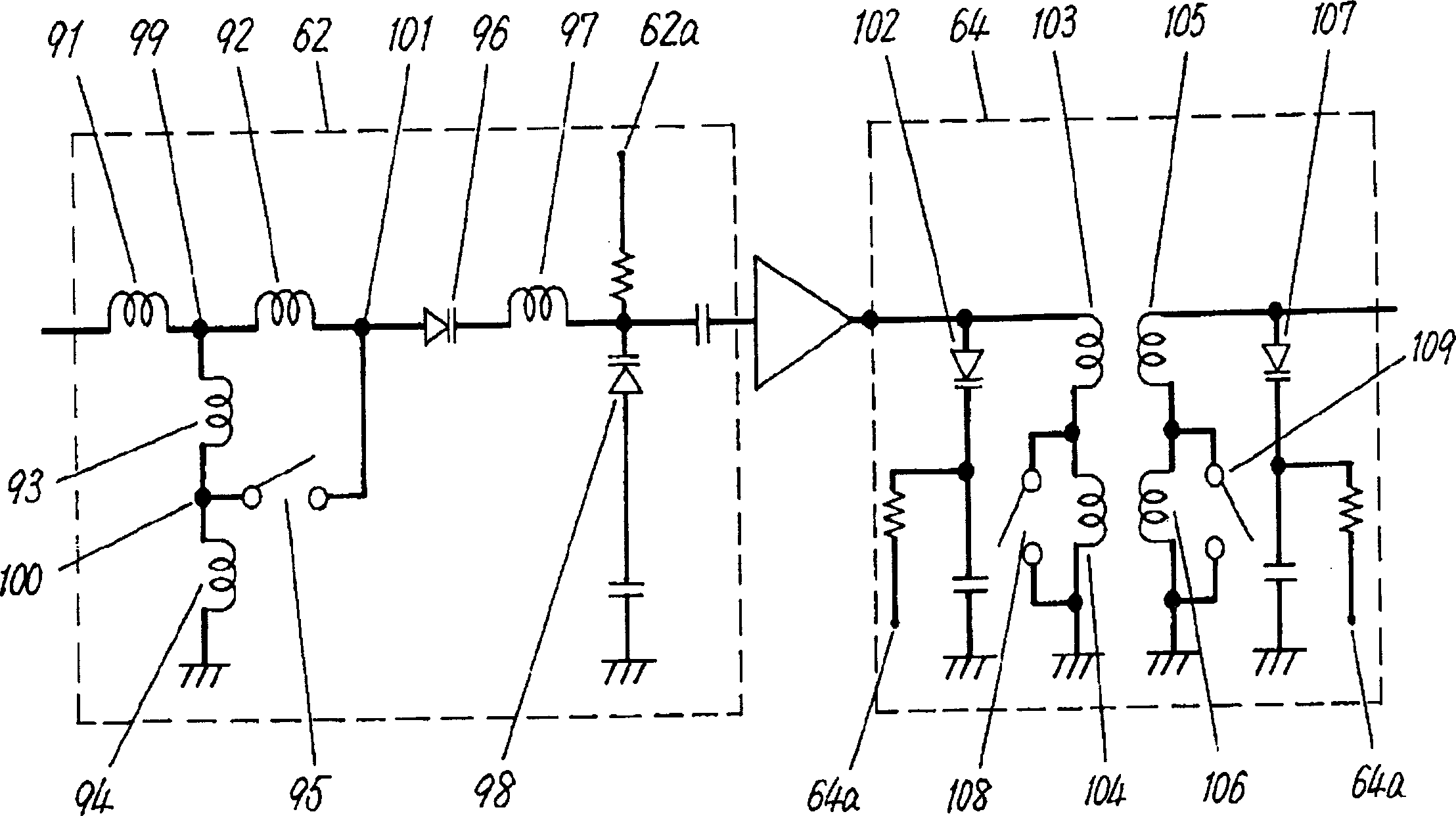
[0101] Hereinafter, a third embodiment of the present invention will be described using the drawings. Image 6 It is a block diagram of main parts of a television receiver using the high-frequency receiving device of the third embodiment. In addition, in the third embodiment, the same reference numerals are attached to the same constituent elements as those in the first embodiment to simplify the description.
[0102] exist Image 6 In this case, a single tuned filter 52 is connected to the input terminal 51 and includes a variable capacitance diode. The tuning frequency of the single-tuning filter 52 is within the UHF broadcast band from 367.25 MHz to 801.25 MHz, and the tuning frequency can be changed by the tuning voltage supplied to the variable frequency terminal 52a.
[0103] A multituned filter 54 is connected to the output of the high frequency amplifier 53 . This multi-tuning filter 54 includes two variable capacitance diodes, and its tuning frequency can be change...
PUM
 Abstract
Description
Claims
Application Information
 - R&D
- Intellectual Property
- Life Sciences
- Materials
- Tech Scout
- Unparalleled Data Quality
- Higher Quality Content
- 60% Fewer Hallucinations
Browse by: Latest US Patents, China's latest patents, Technical Efficacy Thesaurus, Application Domain, Technology Topic, Popular Technical Reports.
© 2025 PatSnap. All rights reserved.Legal|Privacy policy|Modern Slavery Act Transparency Statement|Sitemap|About US| Contact US: help@patsnap.com