
External Cavity Tunable Laser and Control

a tunable laser and external cavity technology, applied in the direction of laser output parameters control, semiconductor laser optical devices, lasers, etc., can solve the problems of low tunability, 4-16 channels, and advanced dfb lasers suffer, so as to avoid lasing instability and negligible effect on tunable laser performan

Inactive Publication Date: 2006-08-31
ROSENBLATT YEHUDA
View PDF0 Cites 53 Cited by
  • Summary
  • Abstract
  • Description
  • Claims
  • Application Information

AI Technical Summary

Benefits of technology

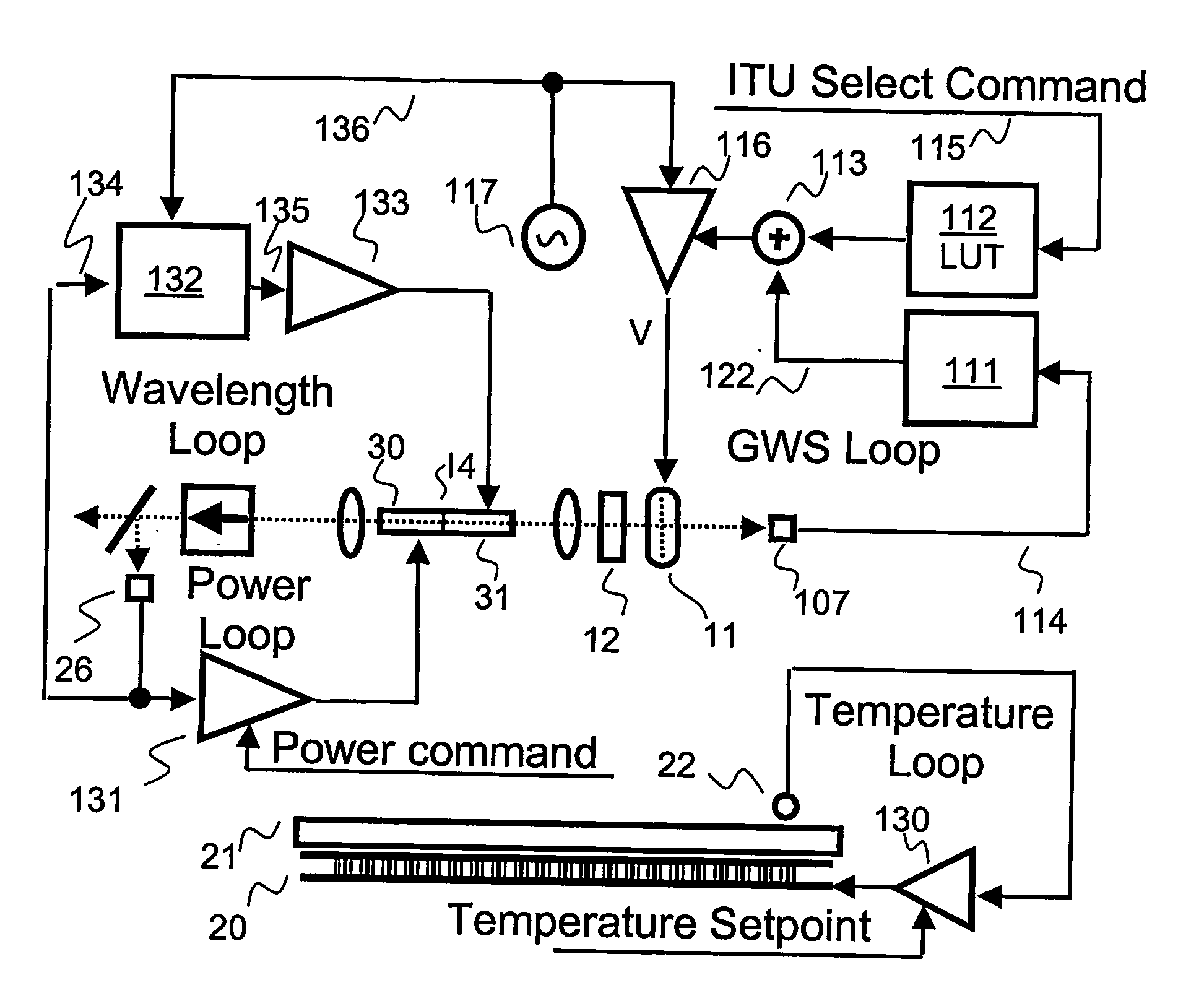
[0010] The proposed tunable laser system preferably comprises, in its simplest form, a gain medium disposed between two end mirrors and an internal etalon to provide basic stability. By using a wavelength selective active tunable mirror such as a GWS, as one of these cavity mirrors, or by using the GWS as an intra-cavity filter, meaning that the filter is disposed between the cavity end reflectors, and by using the etalon both to support the GWS selection of the desired wavelength, and to stabilize the laser wavelength, the operating wavelength of the external cavity tunable laser can be controlled very precisely, and can be rapidly stabilized to the desired wavelength, generally within milliseconds. For DWDM applications, the wavelengths selected are preferably those of the International Telecommunication Union (ITU) grid, for instance, the allowed channels of the C band, or similar.
[0035] The benefits of an intra-cavity etalon in a tunable filter laser can thus be summarized as follows: (i) Increased laser wavelength stability, resulting from reduced dependency on the tunable filter accuracy, the tunable filter noise (frequency shifting), the tunable filter bandwidth and the tunable filter control accuracy and drift. (ii) Increased SMSR due to the narrowness of the etalon bandwidth. (iii) Elimination or reduction of the need for external wave-locking means to the ITU grid. (iv) Wavelength locking by the simple means of power monitoring. (v) Use of the etalon as a compact cavity folding element for output power coupling or / and power monitoring.

Problems solved by technology

Advanced DFB lasers suffer, from low tunability, typically of 4-16 channels only, and low switching speeds of the order of a few milliseconds, since tuning is performed thermally.
The DBR or GSCR type of laser sources can be tuned over a large range of wavelengths, typically 10 to 40 nm., and can be tuned rapidly since the tuning mechanism is not thermal, but they have low power outputs, poor Relative Interference Noise (RIN), relatively wide linewidth, and generally have complicated control systems because of the interaction that takes place between the various sections, and they may have serious aging problems.
However, such a design may suffer from reliability problems because of the moving parts involve, even if in MEMS form, and the control system required may be complex.
In this case also, the control system may be complex and since the tuning is done thermally, low tuning speeds of the order of several seconds are achieved, which may be suitable for some current applications but which are totally unsuitable for more advanced applications of such lasers, such as SONET applications with a recovery time of 50 msec.
Furthermore, such ECDL's may display significant sensitivity to packaging tolerances and to thermal and mechanical deformations errors, which may present problems in providing stable and predictable operation over a wide range of conditions.
However, this patent does not provide details of how to provide sufficiently narrow and stable lasing lines for use in DWDM applications, nor are any details provided of a laser tuning control system to enable such stable use.

Method used


Image

  • External Cavity Tunable Laser and Control
  • External Cavity Tunable Laser and Control
  • External Cavity Tunable Laser and Control

Examples


Embodiment Construction

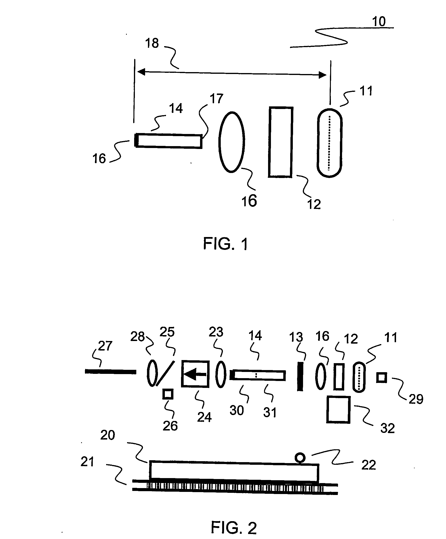
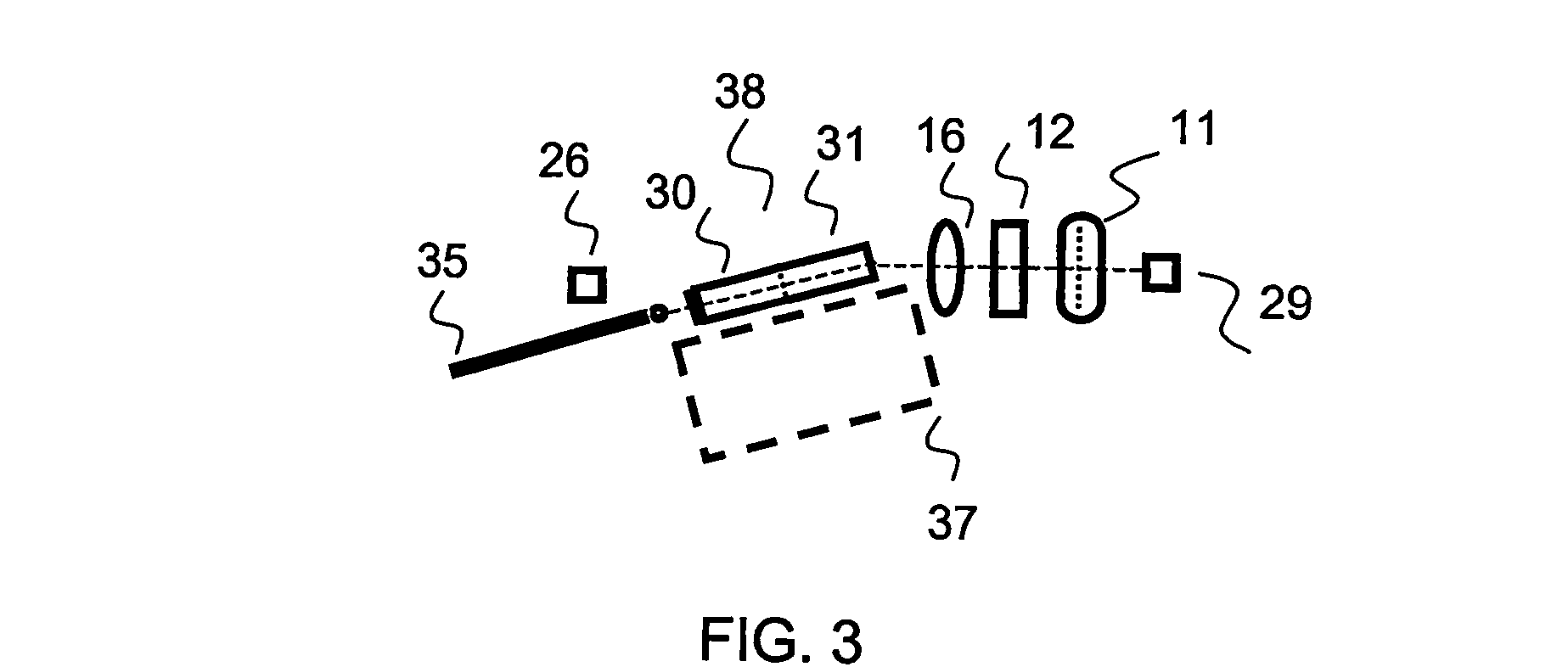
[0067] Reference is now made to FIG. 1, which illustrates schematically an External Cavity (EC) tunable laser 10, constructed and operative according to a first preferred embodiment of the present invention utilizing a tunable filter 11, such as a GWS filter, and an intra-cavity etalon 12. The laser cavity is defined by the region 18 between one end mirror 36 and the GWS element 11, with the gain medium 14 situated therein. The gain medium can be any of the common lasing media, whether solid state, gaseous or liquid. According to a most preferred embodiment, the lasing element 14 is a laser diode chip, and the end mirror 36 is then described as the front facet of the laser diode chip, and this embodiment will be generally used throughout this application to illustrate the various preferred embodiments of the present invention, though it is to be understood that the invention is not meant to be limited to such laser diodes. According to one preferred implementation of the embodiment ...


PUM


Abstract

An optical lasing device, comprising (i) a lasing medium disposed in a lasing cavity, (ii) an etalon disposed within the lasing cavity, and (iii) an electrically tuned filter device, such as a grating waveguide structure device. The lasing device also comprises a detector for determining the lasing power of the lasing device, and a controllable phase shift capability, and the device is preferably locked to a maximum of the lasing power by adjusting the phase, thereby achieving locking to a wavelength predetermined by the etalon, aligned to an ITU grid wavelength. Adjusting the phase shift to achieve the maximum of the lasing power is preferably performed using a closed loop system. Furthermore, adjusting of the phase shift to achieve a maximum of the lasing power is preferably also operative to wave lock the lasing device to a peak wavelength of the etalon.

Description

FIELD OF THE INVENTION [0001] The present invention relates to the field of external cavity, tunable lasers and their control systems, and especially external cavity diode tunable lasers using an active tunable mirror for high speed tuning applications, such as in optical communications networks. BACKGROUND OF THE INVENTION [0002] In recent years, there has been a growing interest in tunable, wavelength-selective filters and sources for use in Dense Wavelength Division Multiplexing (DWDM) systems. A number of different types of such tunable laser sources are known in the prior art for use in such applications, including conventional Distributed Feedback (DFB) type lasers from suppliers such as Fujitsu, Hitachi and NEC, Distributed Bragg Reflection (DBR) or similar type lasers, such as those available from companies such as Agility Inc., and external cavity diode lasers (ECDL), such as those available from companies such as Iolon Inc. and Intel. Inc. [0003] Conventional types of DFB ...

Claims


Application Information

Patent Timeline
Patent Type & Authority Applications(United States)
IPC IPC(8): H01S3/13H01S3/08H01SH01S3/10H01S3/107H01S5/00H01S5/024H01S5/06H01S5/10H01S5/14
CPCH01S3/1062H01S3/107H01S5/005H01S5/0064H01S5/02284H01S5/02415H01S5/02438H01S5/06H01S5/06255H01S5/1039H01S5/141H01S5/02251
Inventor ROSENBLATT, YEHUDA
Owner ROSENBLATT YEHUDA
Learn More