Layer composition of an electrowetting system

a technology of electrowetting system and layer composition, which is applied in the direction of electrolysis components, solid separation, lamination, etc., can solve the problems of reducing the permittivity value, so as to and increase the permittivity value

Inactive Publication Date: 2011-03-22
ADVANCED DISPLAY TECH
View PDF19 Cites 13 Cited by
  • Summary
  • Abstract
  • Description
  • Claims
  • Application Information

AI Technical Summary

Benefits of technology

[0013]A further approach to provide materials with high permittivities is described in U.S. Pat. No. 7,172,947 B2. There, the eligible materials or metal oxides are doped with a non-metal, preferably with nitrogen. The permittivity increase thus achieved is thought to be due to the conversion of the initial crystal structure into a mainly tetragonal crystal structure. This makes it possible to increase the permittivity value by more than 45%.
[0014]The properties of a second or further fluid(s) may contribute as well to the electrowetting effect. Usually, water with a permittivity ∈r of approximately 78 is used as the fluid layer. Alternatively propylene carbonate and γ-butyrolactone may be used, also being colorless fluids. Furthermore, they advantageously have a melting temperature of −43° C., so that displays working with the electrowetting effect may also be used in cold regions where water with its melting temperature of 0° C. would already cause the failure of the device. For this, propylene carbonate is specifically preferred, although its permittivity with ∈r˜65 is considerably higher than the permittivity of γ-butyrolactone with ∈r˜36.
[0015]By optimization of the materials for the individual components of the layer composition, the voltage can be considerably reduced, whilst maintaining the performance of the electrowetting effect, or the respective performance data may be improved when the voltages are increased. Using niobium oxide as the insulator layer, for example, the performance of the electrowetting effect could be maintained when the voltage is decreased from 60 V to 12 V.

Problems solved by technology

However, due to the high permittivity of the used fluids the voltage drop over the drop height is comparatively small.
Very small irregularities in the thickness then result in the drop, inducing a field breakdown with corresponding destruction when it reaches such a site.
A thicker insulator layer, as may be usually used in such cases, is not helpful in this case, as by increasing the layer thickness the field portion in the area of the drop decreases significantly.

Method used


Image

  • Layer composition of an electrowetting system
  • Layer composition of an electrowetting system

Examples


Embodiment Construction

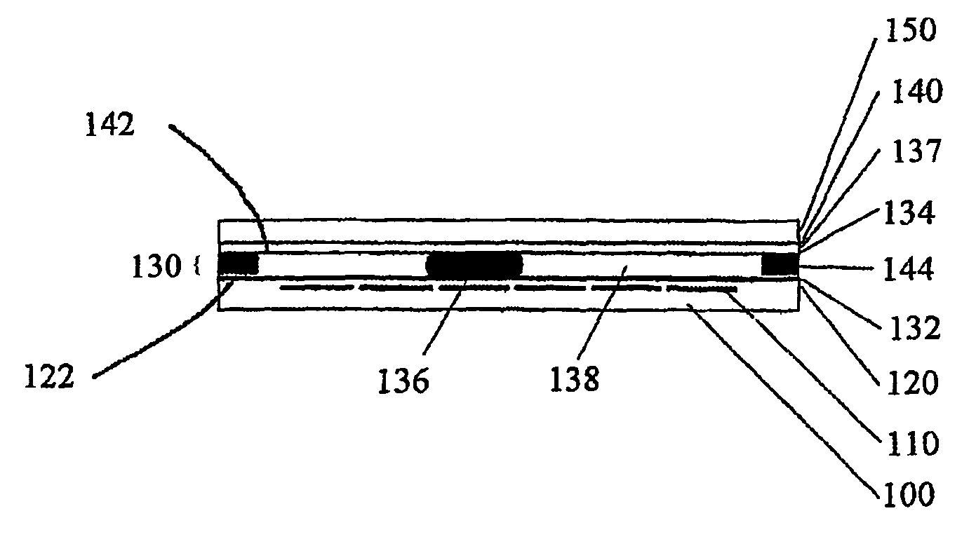
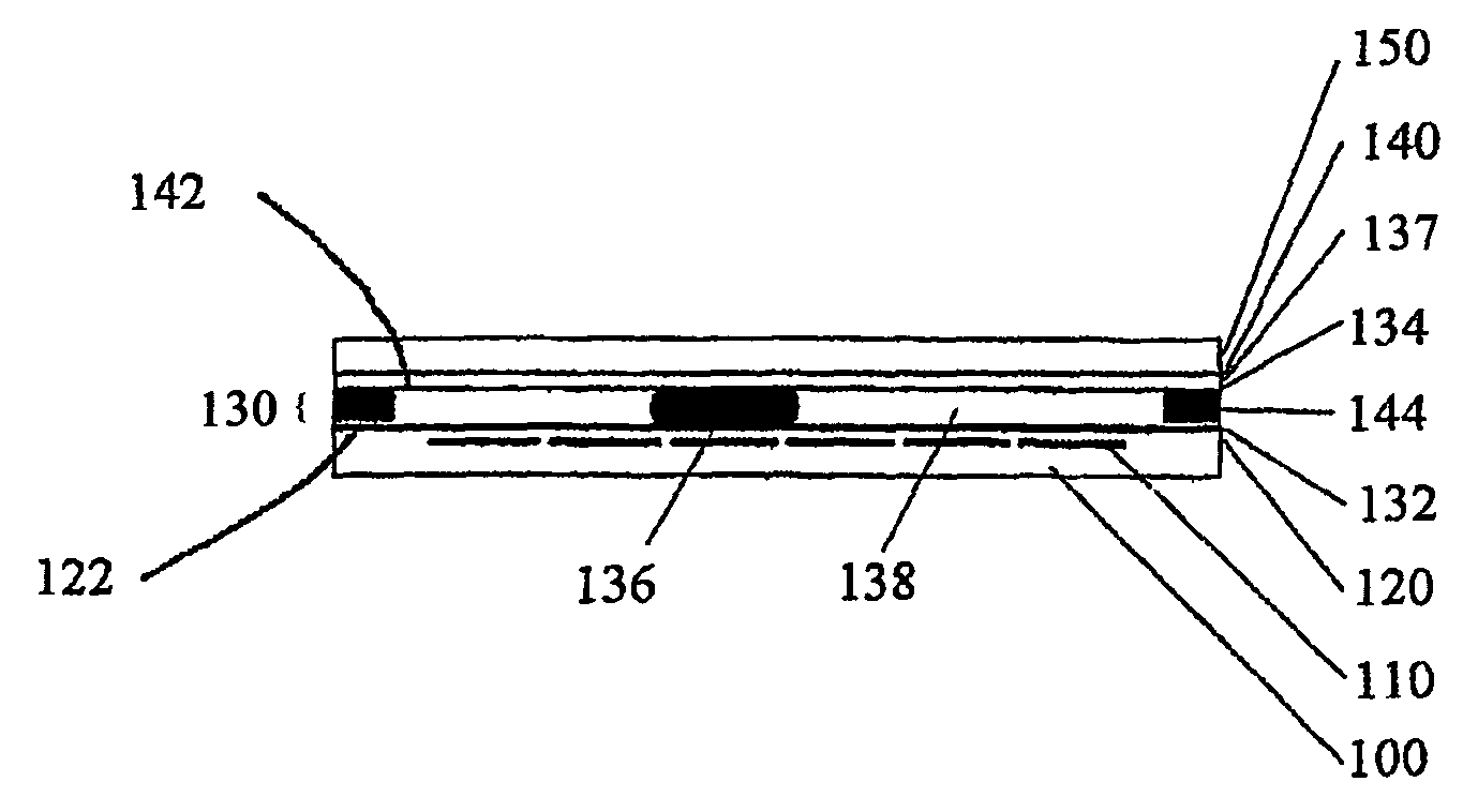
[0026]If in the description, a layer is described as being “on” another layer, it is meant to be directly adjacent to it. If a layer is arranged “over” another layer, one or more layers may be interposed.

[0027]According to the drawing FIGURE, the layer system is built of cells, each having a carrier 100 made of a transparent insulating material. Therein, the thickness of the carrier 100 is based on the expected mechanical stresses or the intended use with the minimum thickness possibly being 5 μm, and the maximum thickness several millimeters. On the carrier 100, an electrode layer 110 is disposed the structuring of which is chosen according to the intended embodiment. On the electrode layer 110, an insulator layer 120 is disposed which is made of a material with a high permittivity of at least 20 according to the invention. Over the insulation layer 120, a repellent layer 132 is disposed, with an interposed adhesion enhancing layer 122 providing good adhesion of the repellent layer...


PUM

PropertyMeasurementUnit
melting temperatureaaaaaaaaaa
thicknessaaaaaaaaaa

Abstract

A layer composition of an electrowetting system with a first electrode layer, an insulator layer on the first electrode layer, and a fluid layer over the insulator layer, wherein the fluid layer comprises at least two immiscible fluids which, under the influence of an applied voltage, reversibly change their wetting behavior of a surface allocated to the insulator layer, wherein the insulator layer being at least in part built of a material with a permittivity of ∈r≧20. The fluid layer is adjacent to at least one layer being repellent for the at least one of the fluids. On the surface of the repellent layer pointing away from the fluid layer is provided an adhesion enhancing layer before the subsequent layer.

Description

BACKGROUND OF THE INVENTION[0001]The invention relates to the layer composition of an electrowetting system with a first electrode layer, an insulator layer on the first electrode layer, and a fluid layer above the insulator layer, with the fluid layer comprising at least two immiscible fluids which, under the influence of an applied voltage, reversibly change their wetting behavior of a surface allocated to the insulator layer.[0002]Such a layer composition is described in the article “Electrowetting Displays” by Johan Feenstra and Rob Hayes, accessible under[0003]http: / / www.liquavista.com / files / LQV060828XYR-15.pdf.[0004]Electrowetting describes a procedure to modify the form of a fluid, or to change its position, by applying an electrical field. The form of a drop is determined by its surface tension relative to the adjacent media. The surface tension is an effect of the associated surface energies, which, in the case of electrowetting, are influenced by an electrostatic contribut...

Claims


Application Information

Patent Timeline
Patent Type & Authority Patents(United States)
IPC IPC(8): C02F1/40B03C5/02B29C65/00G02B26/02
CPCG02B26/005
Inventor BARTELS, FRANKBITMAN, ANDRIYJEROSCH, DIETER
Owner ADVANCED DISPLAY TECH
Why Eureka
Try Eureka