Mobile communication terminal module and mobile communication terminal

a mobile communication terminal and module technology, applied in the direction of radio transmission, electrical equipment, transmitter monitoring, etc., can solve the problems of deteriorating performance of the canceler, taking time to optimize the amplitude and phase, etc., to improve the basic performance of the mobile communication terminal module, improve the basic performance, and accelerate calibration

Inactive Publication Date: 2013-09-19
HITACHI MEDIA ELECTORONICS CO LTD
View PDF1 Cites 52 Cited by
  • Summary
  • Abstract
  • Description
  • Claims
  • Application Information

AI Technical Summary

Benefits of technology

[0016]According to the present invention, it is possible to speed up calibration, it is possible to highly accurately compensate the deterioration of performance d

Problems solved by technology

However, in the case where variations occur due to devices, power supply voltage, and temperature, such a problem arises in that the performance of the canceler deteriorates.
Moreover, although cal

Method used


Image

  • Mobile communication terminal module and mobile communication terminal
  • Mobile communication terminal module and mobile communication terminal
  • Mobile communication terminal module and mobile communication terminal

Examples


first embodiment

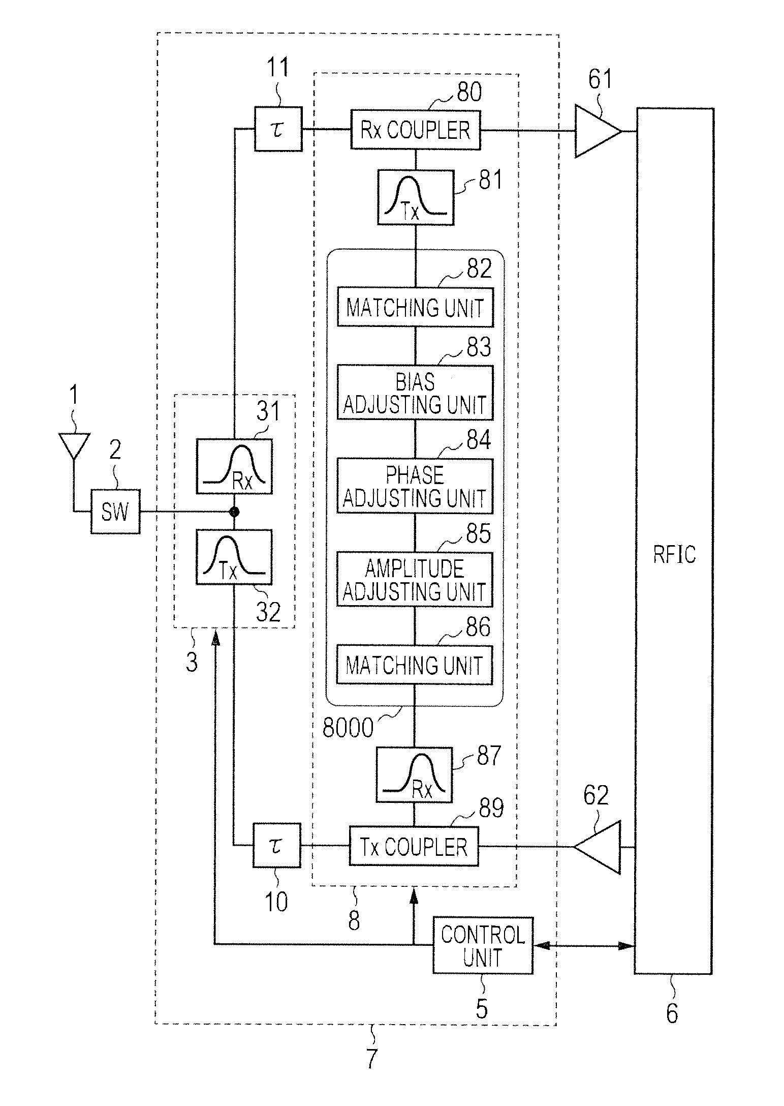
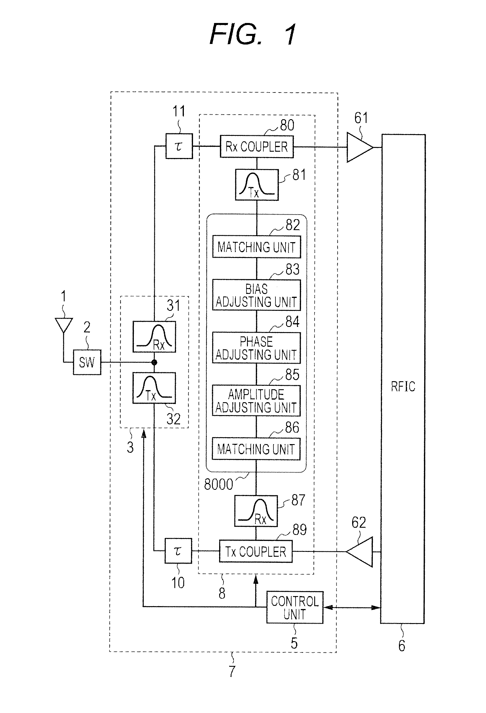
[0031]FIG. 1 is a block diagram of an exemplary configuration of a mobile communication terminal module according to a first embodiment. The configuration of the embodiment is targeted for mobile communication terminal modules in the WCDMA mode and the LTE mode, for example. However, the configuration of the embodiment is not limited thereto. The configuration of the embodiment is also used for mobile communication terminal modules in which different bands are allocated to the transmit frequency and the receive frequency for simultaneously operating transmission and reception.

[0032]First, the flows of a transmit signal and a receive signal will be described. A tunable filter 3 is configured of a Tx filter 32 and an Rx filter 31, and connected to a transmission system including an antenna SW (switch) 2 and a PA (Power Amplifier) 62, and to a reception system including an LNA (Low Noise Amplifier) 61. A transmit signal outputted from an RFIC 6 is inputted to the PA 62, and amplified t...

second embodiment

[0085]FIG. 11 is a block diagram of an exemplary configuration of a mobile communication terminal module according to a second embodiment. Since the flows of the transmit signal and the receive signal are the same as in the first embodiment, the description is omitted. Here, a signal to cancel the leakage component of the transmit signal at the output of a PA 62 is generated at a canceler 8, and a signal to cancel the leakage component of thermal noise in the reception band is generated at a canceler 9. The canceler 8 includes a noise canceler 88 that removes thermal noise in the reception band, and the canceler 9 includes a Tx canceler 98 that removes a transmit signal.

[0086]In the following, blocks configuring the canceler 8 and the canceler 9 will be described in detail.

[0087]A transmission side coupler 89 is loosely coupled to a transmission system, and leads a transmit signal and thermal noise in the reception band attenuated by about 10 dB into the canceler 8. On the other han...

third embodiment

[0095]FIG. 12 is a block diagram of an exemplary configuration of a mobile communication terminal module according to a third embodiment. Since the flows of the transmit signal and the receive signal are the same as in the first embodiment, the description is omitted. Here, a signal to cancel the leakage component of a transmit signal at the output of a PA 62 and a signal to cancel the leakage component of thermal noise in the reception band are generated at a canceler 8. A signal path is branched in the canceler 8, a signal to cancel the transmit signal is generated on one of the branched paths and a signal to cancel thermal noise in the reception band is generated on the other of the branched paths. A system to generate a signal to cancel the transmit signal includes a noise canceler 837 that removes thermal noise in the reception band, and a system to generate a signal to cancel thermal noise in the reception band includes a Tx canceler 839 that removes the transmit signal.

[0096]...


PUM


Abstract

In a tunable duplexer combining a tunable filter with a canceler, calibration for optimizing passband characteristics and stop band characteristics is accelerated, and the deterioration of performance due to variations is highly accurately compensated. The tunable filter is calibrated to acquire isolation characteristics, and then coarse calibration and fine calibration are performed on the canceler. In coarse calibration, the use band of the tunable filter is set to a suppression band, and the isolation characteristics of the canceler are acquired. An amplitude, a phase, and a bias voltage are adjusted based on a result of comparison with the acquired isolation characteristics of the tunable filter for determining an approximate convergence. Fine calibration is further performed, and the optimum point is determined in a narrow range near the convergence.

Description

INCORPORATION BY REFERENCE[0001]This application relates to and claims priority from Japanese Patent Application No. 2011-276060 filed on Dec. 16, 2011, the entire disclosure of which is incorporated herein by reference.BACKGROUND OF THE INVENTION[0002]1. Field of the Invention[0003]The present invention relates to a mobile communication terminal module and a mobile communication terminal. More particularly, the present invention relates to a mobile communication terminal module and a mobile communication terminal conforming to wireless communication systems such as the WCDMA (Wideband Code Division Multiple Access) mode and the LTE (Long Term Evolution) mode, for example.[0004]2. Description of the Related Art[0005]In the mobile telephone, the adaptation of the LTE mode is being considered in addition to the WCDMA already in practical use. Since transmission and reception are operated simultaneously in the WCDMA mode and the LTE mode, different bands are used for the transmit frequ...

Claims


Application Information

Patent Timeline
IPC IPC(8): H04L5/14
CPCH04L5/14H04B17/11H04B1/52
Inventor TONE, MASAZUMIYAMAMOTO, AKIOSHIBA, TAKASHIHIKINO, OSAMU
Owner HITACHI MEDIA ELECTORONICS CO LTD
Why Eureka
Try Eureka