
Self-calbrating RFID transponder

a transponder and self-calbrating technology, applied in the field of rfid transponders, can solve the problem that the second calibration step is practically never performed, and achieve the effect of speeding up the calibration

Active Publication Date: 2009-07-09
TEXAS INSTR INC
View PDF7 Cites 2 Cited by
  • Summary
  • Abstract
  • Description
  • Claims
  • Application Information

AI Technical Summary

Benefits of technology

[0006]The self-calibrating stage can include an adder stage. The adder stage can be used to add a previous calibration value to a current calibration value. A second way to add the new calibration value to the previously calibration value is to start the second counter (i.e. e.g. the UP / DOWN counter) not from zero, but load the previously calibration value into the second counter at the beginning of the interrogation phase. In this case no adder stage is necessary. If the self-calibration is performed during a final stage of the manufacturing process and then repeated later, it can be very advantageous to do calibration based on the previous value. This can speed up the calibration and be used for finer calibration in a second self-calibration step.

Problems solved by technology

Actually, a second calibration step is practically never performed.

Method used


Image

  • Self-calbrating RFID transponder
  • Self-calbrating RFID transponder
  • Self-calbrating RFID transponder

Examples


Embodiment Construction

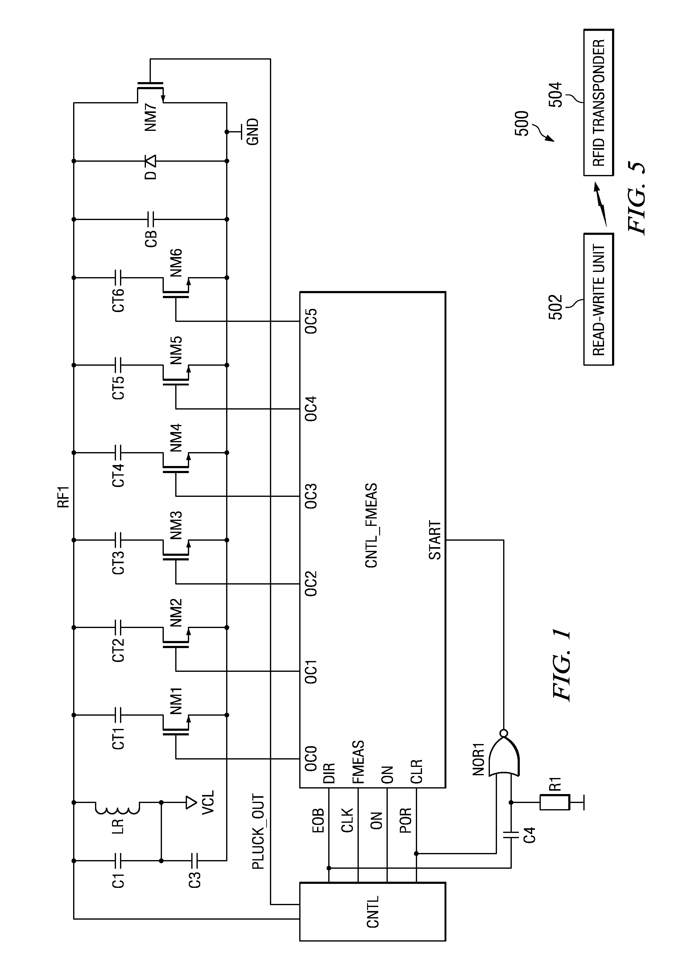
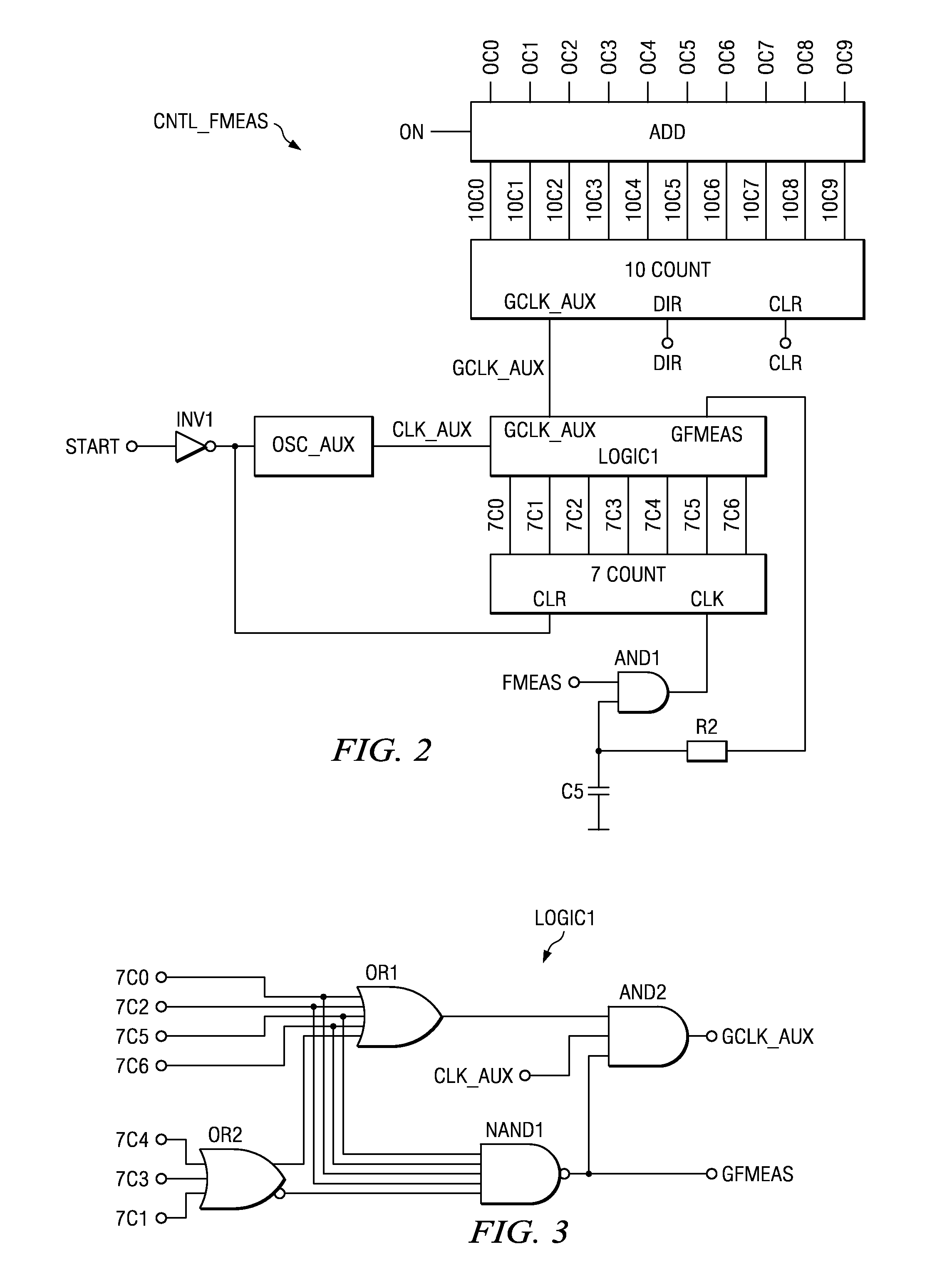
[0018]FIG. 1 shows a simplified circuit diagram of an embodiment of the present invention. The resonant circuit comprises the resonant capacitor CR and the inductive antenna LR. The resonant circuit is coupled through capacitor C3 to ground. C3 works as buffer capacitor for VCL. There is further a diode D operating as a simple rectifier and an internal capacitor CB (CB represents a parasitic capacitor). The internal supply voltage VCL is generated if an external radio frequency signal is received through antenna LR. The received RF signal is present at node RF1. The node RF1 is coupled to the control stage CNTL. The control CNTL derives the output signals CLK, EOB, ON and POR from the signal at node RF1, i.e. the RF signal. If now external RF signal is present, the resonant circuit CR, LR is excited through transistor NM7 which is controlled by the control signal PLUCK_OUT. The control stage CNTL is a conventional control stage producing the end of burst signal EOB, the clock signal...


PUM

PropertyMeasurementUnit
radio frequencyaaaaaaaaaa
frequencyaaaaaaaaaa
frequencyaaaaaaaaaa

Abstract

A RFID transponder includes a resonant circuit for providing a clock signal at a predetermined clock frequency, a self-calibration stage for calibrating the resonant circuit's current clock frequency towards the predetermined clock frequency. The self-calibration stage is adapted to compare a first clock frequency of the resonant circuit determined during an interrogation period, during which the resonant circuit is excited by an external RF signal, with a second clock frequency determined during a frequency maintenance period, during which the resonant circuit is excited internally through an oscillation maintenance circuit of the RFID transponder and to calibrate the resonant circuit towards the predetermined clock frequency based on the comparison result.

Description

FIELD OF THE INVENTION[0001]The present invention relates to a RFID transponder, and more specifically the present invention relates to a method and circuitry for calibrating a RFID transponder. The present invention relates also to a system with a RFID transponder.BACKGROUND OF THE INVENTION[0002]RFID transponders are used for all kinds of identification tasks. They can contain data which is written to or read out by read / write units (R / W-units) in a downlink or uplink data transmission, respectively. The antenna of a RFID transponder is typically built with an inductive loop. This inductor is coupled to a capacitor to form a resonant circuit. During downlink data transmission, the resonant circuit is excited by a radio frequency signal (e.g. 134 kHz). Being subject to the external RF excitation, the resonant circuit starts oscillating. In an uplink data transmission phase, the RFID must perform an oscillation with the resonant circuit, which is then received by the R / W unit. An im...

Claims


Application Information

Patent Timeline
Patent Type & Authority Applications(United States)
IPC IPC(8): H04Q5/22G01R31/28
CPCG06K19/0723H03J5/244Y10T29/49004H03J2200/29H04B1/59H03J2200/10
Inventor HERTWIG, BERND
Owner TEXAS INSTR INC
Learn More