Colorimetric imaging system

a colorimetric imaging and color image technology, applied in the field of electronic color image acquisition, can solve the problems of no camera or scanner, no way to retrieve the actual color from the digital image, and no universal definition of the three primaries

Inactive Publication Date: 2004-07-06
CAMBRIDGE RES & INSTR
View PDF15 Cites 50 Cited by
  • Summary
  • Abstract
  • Description
  • Claims
  • Application Information

AI Technical Summary

Problems solved by technology

There are problems with this approach.
First, the definition of the three primaries is not universal amongst all manufacturers and all types of equipment.
The reason for this problem is that the color response of the camera weights different wavelengths of light differently from how the human eye does.
There is no way to retrieve the actual color from the digital image, once it has been captured in non-colorimetric terms.
No cameras or scanners in the prior art record the colors using the same color response that the human eye affords.
As a result, color fidelity of digital images is lost at the time the image is captured.
Another problem occurs when one seeks to transform between an RGB color representation of a scene and other color representations such as cyan-yellow-magenta-black (CMYK) that is used in printing.
This can lead to further degradation of color fidelity.
Since the RGB color image is ambiguous in the sense that the camera or scanner used to record it has a color response that is not the same as the color perception response of the eye, the color error in the original color space can be increased when transforming to another color space.
Another problem relates to the fact that the color error of different cameras is not the same, and further depends on the hues being captured.
If the transformation matrix is optimized for a certain range of colors or wavelengths, other colors will not be transformed well.
Similarly, a transformation that works adequately for one camera (with its attendant color error properties) may not work well

Method used


Image

  • Colorimetric imaging system
  • Colorimetric imaging system
  • Colorimetric imaging system

Examples


Embodiment Construction

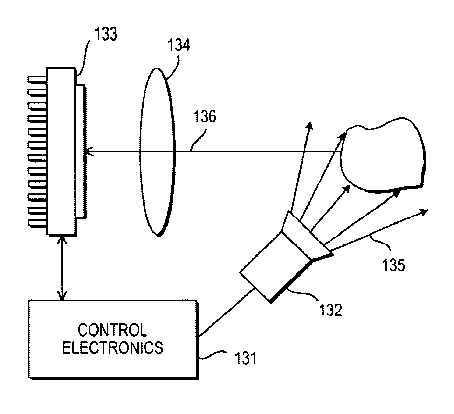
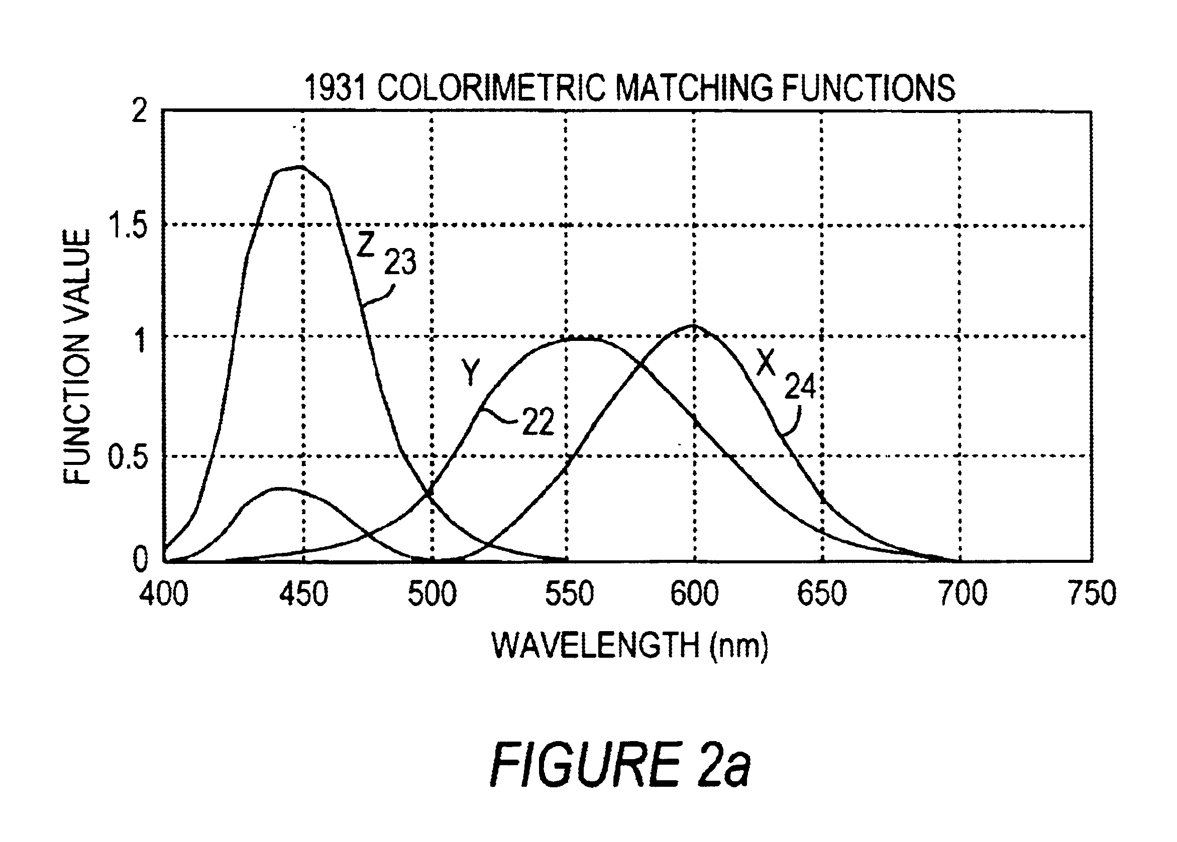
The embodiments shown make use of a detector with a certain spectral response, and an illumination system or a filtration system which accommodates this spectral response and further imposes either the X, the Y, or the Z colorimetric weighting function. That is, the filter or illumination system has a spectral response given by:

F.sub.x (.lambda.)=k.sub.x X(.lambda.) / D(.lambda.) [1a]

F.sub.y (.lambda.)=k.sub.y Y(.lambda.) / D(.lambda.) [1b]

F.sub.z (.lambda.)=k.sub.z Z(.lambda.) / D(.lambda.) [1c]

Where:

K.sub.i are scalar constants

F.sub.i (.lambda.) is the relative spectral content of the filter or spectral illuminator at wavelength .lambda.

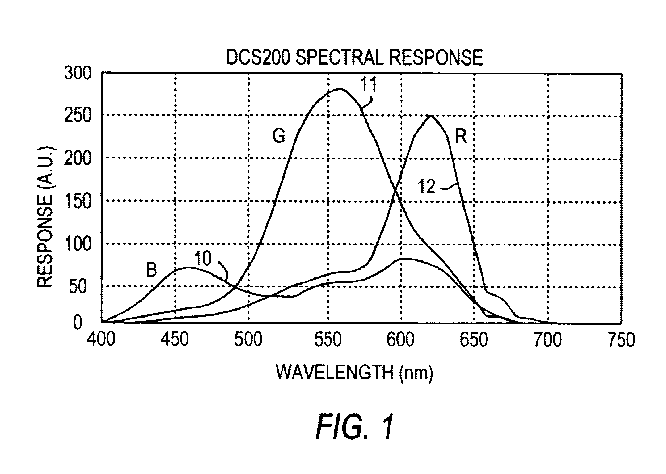
D(.lambda.) is the spectral responsivity of the detector

In this way, the system takes three exposures which comprise the X, Y, and Z content of the scene presented to the camera, with overall signal levels multiplied by arbitrary scale factors. It is necessary to calibrate the scale factors k.sub.i, and to take into account the relative exposure time use...


PUM


Abstract

The present invention provides for an imaging system that obtains, as well as a method for obtaining, the colorimetric value of a plurality of points in a scene when the scene is lit by a source of illumination. The system comprises an imaging detector, imaging optics that receive light from the scene and direct it to the detector, a tunable filter responsive to applied electrical signals that filters the spectrum of light passing therethrough, and a control circuit for acquiring and storing a plurality of images from the detector while the tunable filter expresses a plurality of predetermined filter response functions in response to applied electrical signals, and for determining the colorimetric values from the stored images, wherein each of the filter response functions has substantial transmission at a plurality of wavelengths.

Description

1. Field of the InventionThe invention pertains to electronic color image acquisition, as well as digital image storage, retrieval and transmission.2. Description of the Related ArtDigital images are normally captured in RGB color space, meaning that each pixel or point in the image is characterized by three values indicating the amount of red, green, and blue light present at that point. Typically, the filters used (either in a mosaic or in a sequential color system) partition the light energy into three bands according to wavelength, so the shortest wavelengths are recorded as blue, the middle range as green, and the longest range as red. Typically the blue range is 400-490 nm, green is 490-580 nm, and red is 590-660 nm. Then, the overall signal levels of red, green, and blue are adjusted to achieve a white balance. Often, color-correction matrix is applied to increase color separation, normally in the form of a non-diagonal 3.times.3 matrix that is multiplied by the raw [R, G, B]...

Claims


Application Information

Patent Timeline
IPC IPC(8): G01J3/51G01J3/26G01J3/28G01J3/12H04N9/04H04N1/48G01J3/46
CPCG01J3/26G01J3/2823G01J3/51H04N1/482H04N9/045G01J3/462G01J3/465G01J2003/467H04N2209/043H04N23/84
Inventor MILLER, PETER J.
Owner CAMBRIDGE RES & INSTR
Why Eureka
Try Eureka