Integrated spectroscopy system

a spectroscopy system and integrated technology, applied in the field of optical spectroscopy systems, can solve the problems of poor mechanical stability, large device size, high cost of manufacture of these devices, etc., and achieve the effects of reducing size, increasing stability, and lowering power consumption

Active Publication Date: 2005-04-21
EXCELITAS TECH
View PDF4 Cites 50 Cited by
  • Summary
  • Abstract
  • Description
  • Claims
  • Application Information

AI Technical Summary

Benefits of technology

[0012] Specifically, it is directed to the integration of a tunable Fabry-Perot system with a source system and / or detector system. The use of the Fabry-Perot filter system allows for a high performance, low cost device. The integration of the filter system with the source system and / or detector system results in a device with a small footprint. Further, in the preferred embodiment, the filter system is based on microelectromechancial systems (MEMS), which yield a highly mechanically robust system.
[0015] Temperature control is preferably provided for the system. Currently this is provided by a heater, which holds the temperature of the system above an ambient temperature, or a thermoelectric cooler. For example, the thermoelectric cooler is located between the bench and the package to control the temperature of the source system, tunable Fabry-Perot filter system, and / or the detector system. As a result, a single cooler is used to control the temperature of the filter and SLED chip, lowering power consumption, decreaseing size, while increasing stability.
[0016] In the preferred embodiment, the source system comprises a broadband source. This can be implemented using multiple, spectrally multiplexed diode chips. Preferably, superluminescent light-emitting diodes (SLEDs) are used. These devices have a number of advantages relative to other sources, such incandescent sources. Specifically, they have better spectral brightness, longer operating lifetimes, and a smaller form factor.
[0017] In order to increase the spectral accuracy of the system, a tap can also be used to direct a part of the tunable signal to a detector. A spectral reference, such as a fixed etalon with multiple spectral transmission peaks is placed between the detector and the tap, in order to create a fringe pattern on the detector during the scan, thereby enabling monitoring of the wavelength of the tunable signal. An optical power tap can also be included to monitor the real time emitted optical power during the scan.
[0021] Finally, in the preferred embodiment, isolation is provided between the source system and the tunable Fabry-Perot filter system. This prevents back reflections from the filter into the source system that can disturb the operation of the source system. In one example, an isolator is installed on the optical bench between the SLED and the tunable filter. A quarter wave plate can also be used. This rotates the polarization of the returning light so that it is not amplified by the highly polarization anisotropic SLED gain medium. In another embodiment, the isolation is provided on the bench, with the tunable Fabry-Perot filter system and the detector system.

Problems solved by technology

The drawbacks associated with the prior art spectrometers arise from the large size of the devices combined with the high cost to manufacture these devices combined with poor mechanical stability.
These factors limit the deployment of spectrometers to applications that can justify the investment required to purchase these devices and further accommodate their physical size.
The integration of the filter system with the source system and / or detector system results in a device with a small footprint.

Method used


Image

  • Integrated spectroscopy system
  • Integrated spectroscopy system
  • Integrated spectroscopy system

Examples


first embodiment

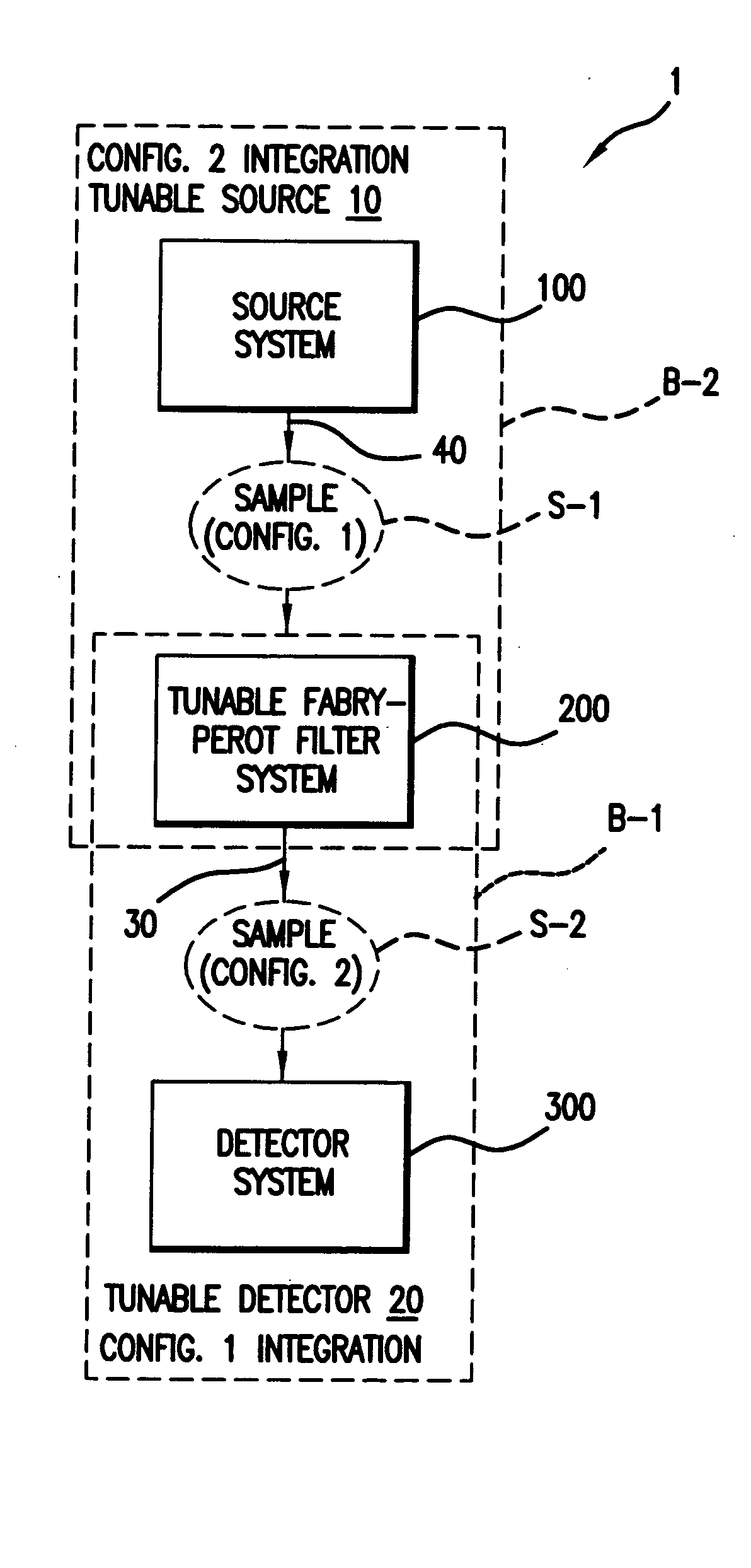
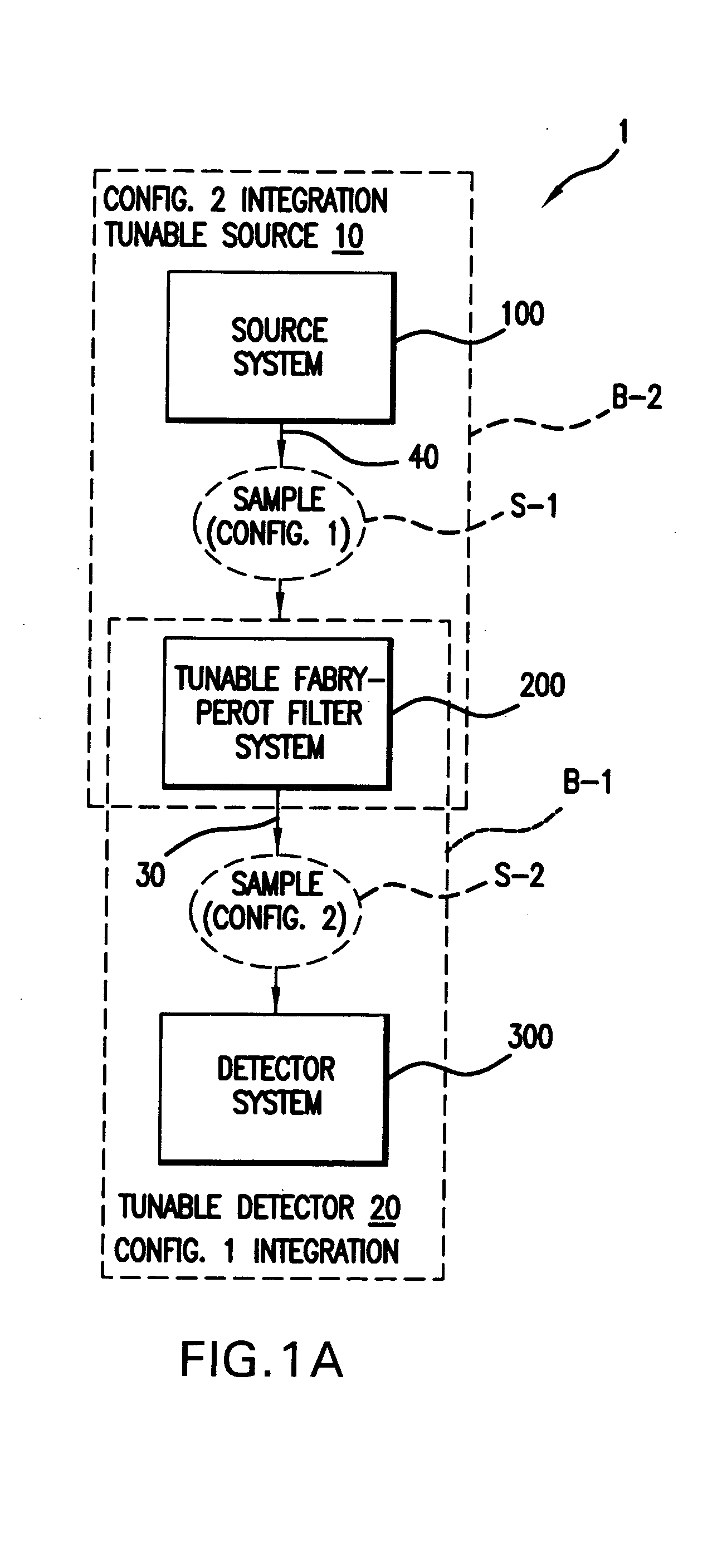
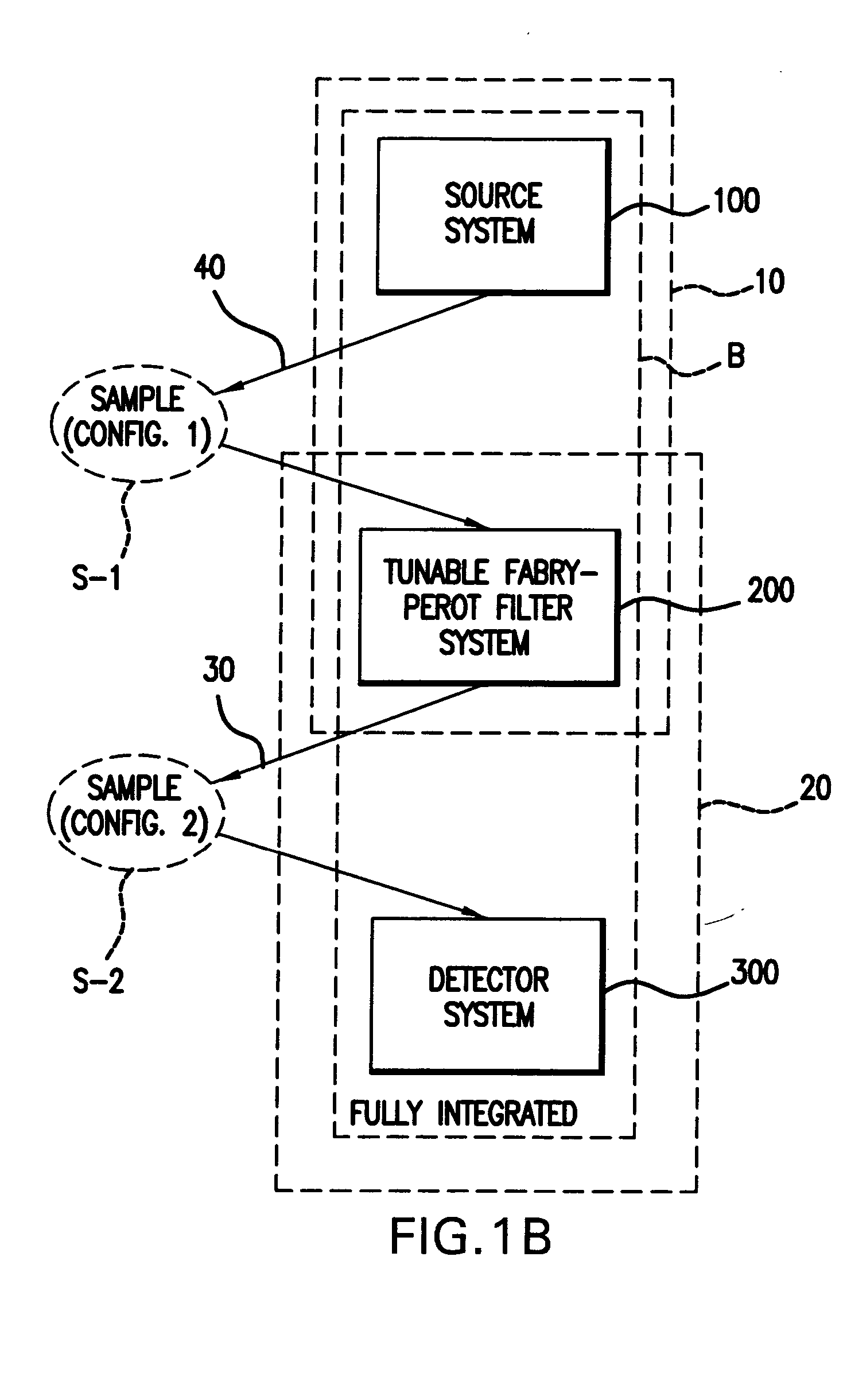
[0053]FIG. 2 illustrates the tunable source 10. Specifically, in this embodiment, the bench B-2 holds the tunable Fabry-Perot filter system 200 and the source system 100 on a common planar surface. The generated tunable signal 30 is coupled off of the bench B-2 by an optical fiber 102. In the preferred embodiment, this optical fiber 102 is a single transverse mode fiber. This has advantages in that it renders the tunable signal 30 very stable, even in the event of mechanical shock to the single mode fiber 102.

[0054] The source system 100 is implemented using, in this embodiment, a superluminescent light emitting diode (SLED) 110. The diode 110 is installed on a submount 112. The submount 112 is, in turn, installed on the bench B-2. In the preferred embodiment, the SLED chip 110 is solder bonded to the submount 112, which further includes metallizations 114 to facilitate wire bonding to provide electrical power to the SLED chip 110. Further, the submount 112 is solder bonded to the b...

second embodiment

[0105]FIG. 12B shows an operationally similar tunable optical filter system 10, for the purposes of the present invention. Reference numerals have been used for functionally equivalent parts. The differential between the two designs lies in the design of the detector system 300. This second embodiment utilizes only a single detector 324, 54 that detects both the optical reference and the optical signal. In this illustration, the package is not shown for clarity.

[0106]FIG. 13 shows another embodiment of the tunable detector 20. The signal from the target is transmitted to the detector 20 via fiber 310. A first lens component 316 collimates the light from the fiber. Second lens components 318 couple the light into the tunable filters 116A, 116B of the filter system 200. Third lens components 322 focus the light to the detector system 300.

[0107] This version uses two tunable filters 116A, 1116B, each filtering a portion of the scan band. Corresponding detectors 334A, 334B detect the t...


PUM

PropertyMeasurementUnit
wavelength rangesaaaaaaaaaa
distanceaaaaaaaaaa
spectroscopyaaaaaaaaaa

Abstract

Integrated spectroscopy systems are disclosed. In some examples, integrated tunable detectors, using one or multiple Fabry-Perot tunable filters, are provided. Other examples use integrated tunable sources. The tunable source combines one or multiple diodes, such as superluminescent light emitting diodes (SLED), and a Fabry Perot tunable filter or etalon. The advantages associated with the use of the tunable etalon are that it can be small, relatively low power consumption device. For example, newer microelectrical mechanical system (MEMS) implementations of these devices make them the size of a chip. This increases their robustness and also their performance. In some examples, an isolator, amplifier, and / or reference system is further provided integrated.

Description

BACKGROUND OF THE INVENTION [0001] Minimally, optical spectroscopy systems typically comprise a source for illuminating a target, such as a material sample, and a detector for detecting the light from the target. [0002] Further, some mechanism is required that enables the resolution of the spectrum of the light from target. This functionality is typically provided by a spectrally dispersive element. [0003] One strategy uses a combination of a broadband source, detector array, and grating dispersive element. The broadband source illuminates the target in the spectral scan band, and the signal from the target is spatially dispersed using the grating, and then detected by an array of detectors. [0004] The use of the grating, however, requires that the spectroscopy system designer make tradeoffs. In order to increase the spectral resolution of these systems, aperturing has to be applied to the light provided to the grating. As more spectral resolution is required, more light is required...

Claims


Application Information

Patent Timeline
Patent Type & Authority Applications(United States)
IPC IPC(8): B81B7/02G01J3/10G01J3/26G01J3/36G01N21/25G02B5/28G02B26/00
CPCG01J3/0256G01J3/10G01N21/255G01J3/36G01J3/26
Inventor ATIA, WALID A.FLANDERS, DALE C.KOTIDIS, PETROSKUZNETSOV, MARK E.
Owner EXCELITAS TECH
Why Eureka
Try Eureka