Eureka AIR delivers breakthrough ideas for toughest innovation challenges, trusted by R&D personnel around the world.

Leather belt wheel for driving belt and belt driving apparatus

A technology of belt drive and pulley, applied in the direction of transmission, belt/chain/gear, hoisting device, etc., can solve the problems of insufficient utilization and increase the manufacturing cost of flat wheel, so as to avoid friction loss and improve durability. Effect

Inactive Publication Date: 2005-02-09
BANDO CHEM IND LTD
View PDF1 Cites 3 Cited by
  • Summary
  • Abstract
  • Description
  • Claims
  • Application Information

AI Technical Summary

Problems solved by technology

[0005] However, when the above-mentioned groove processing is carried out on the flat edge wheel, the manufacturing cost of the flat edge wheel will be increased, and it is difficult to reliably prevent the meandering and deviation of the flat transmission belt only by groove processing.
For this reason, the actual situation of the flat belt drive is that, compared with other belts such as V-ribbed arch belts, although the loss caused by belt deflection is small and the transmission efficiency is very high, it is not fully utilized.

Method used


Image

  • Leather belt wheel for driving belt and belt driving apparatus
  • Leather belt wheel for driving belt and belt driving apparatus
  • Leather belt wheel for driving belt and belt driving apparatus

Examples


Embodiment Construction

[0030] Hereinafter, specific embodiments of the present invention will be described in detail with reference to the accompanying drawings.

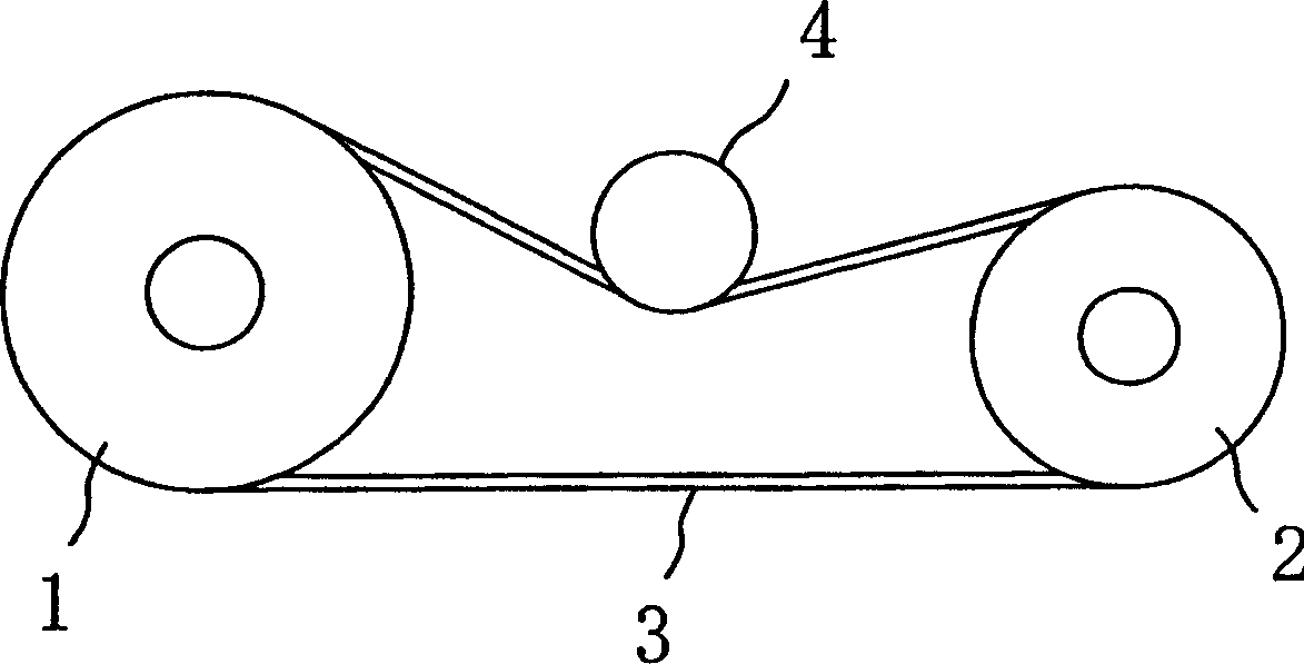
[0031] exist figure 1 In the belt drive shown, 1 represents the driving pulley (flat edge pulley), and 2 represents the driven pulley (flat edge pulley). These two pulleys 1 and 2 are wound with a flat transmission belt 3, and the flat edge pulley 3 is connected to the pulley 4 crimping.

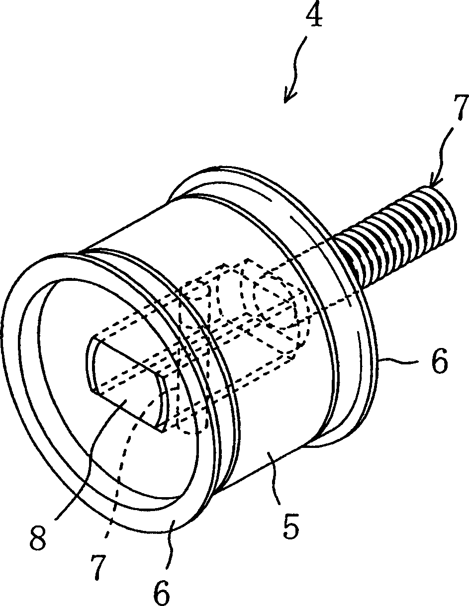
[0032] pulley 4 as figure 2 As shown, it has: a pulley body 5 with a flat transmission belt 3 wound around it, transmission parts 6 and 6 arranged on both sides of the pulley body 5, a supporting mechanism that supports the pulley body 5 and transmission parts 6 and 6 and enables them to swing freely 7. The support mechanism 7 is composed of a support rod 8 and a pivot 9 .

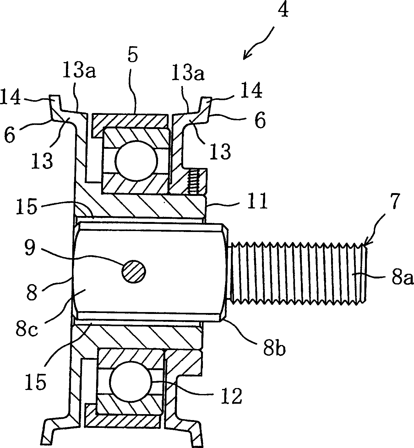
[0033] Such as image 3 As shown, the pulley body 5 is supported by the cylindrical shaft member 11 by the bearing 12, and is freely rotatable. The transmission member 6 on o...


PUM


Abstract

A pulley body 5 is provided at its both sides with power transmission members 6, 6. When a flat belt 3 becomes misaligned relative to the center of the pulley body 5 and comes into contact with one of the power transmission members 6, a running force of the flat belt 3 is utilized to displace the pulley body 5 diagonally relative to the flat belt 3, thus producing a force for returning the flat belt 3 to its original state.

Description

technical field [0001] The invention relates to a pulley for a transmission belt and a belt transmission device. Background technique [0002] In a transmission device using a flat transmission belt, the flat transmission belt sometimes moves in a meandering motion during operation, and sometimes runs offset to one side of the pulley. This is because the flat transmission belt is more sensitive to changes in the structural elements of the transmission device, such as the displacement of the pulley shaft from the normal position, the deflection of the pulley shaft due to the change of the shaft weight, and the swing of the pulley, compared with other transmission belts. When producing such snaking and offset running conditions, the flat transmission belt contacts the flange of the flat-rim wheel, burrs will appear on the side of the flat-rim wheel, and the core wire will be worn. [0003] In response to this problem, there is known a technique of adding a convex surface to t...

Claims


Application Information

Patent Timeline
Patent Type & Authority Applications(China)
IPC IPC(8): F16H7/08F16H7/18F16H55/36F16H55/38
CPCF16H2007/0865F16H7/18F16H2055/363F16H55/36
Inventor 宫田博文西川真一郎
Owner BANDO CHEM IND LTD
Why Eureka
Eureka Blog
Learn More