

Device for applying varnish to electric wire and method of applying varnish
一种电线、调节装置的技术,应用在电线上漆装置领域,能够解决失去电绝缘和热绝缘性能、破裂、绝缘层易于受损等问题
- Summary
- Abstract
- Description
- Claims
- Application Information
AI Technical Summary
Problems solved by technology
Method used
Image

Examples
Embodiment approach 1
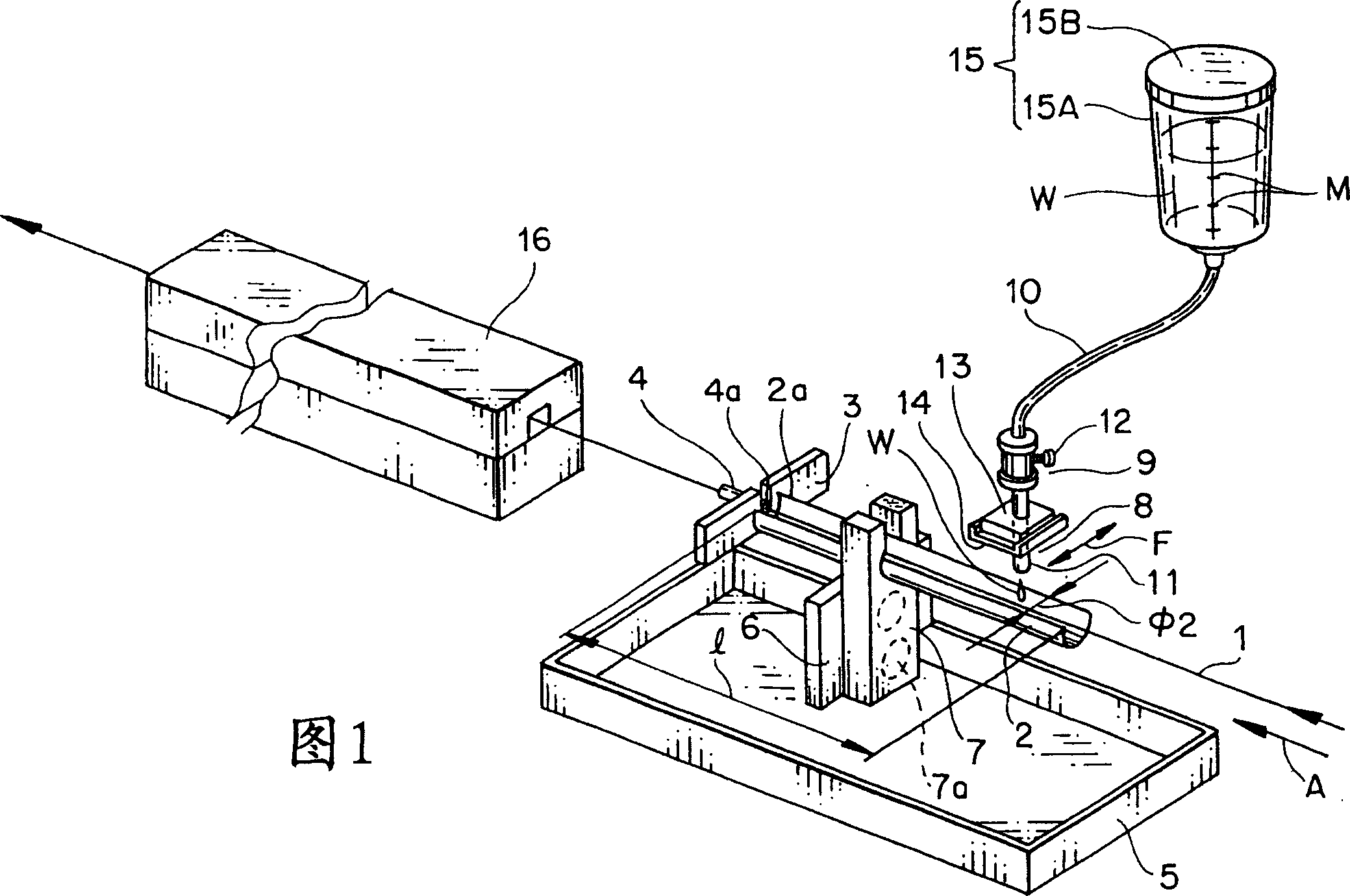
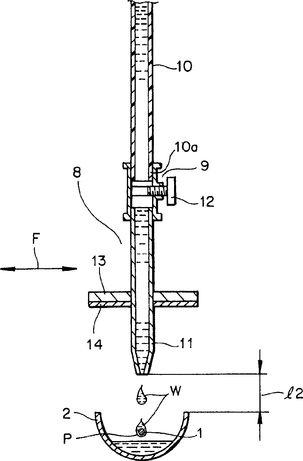
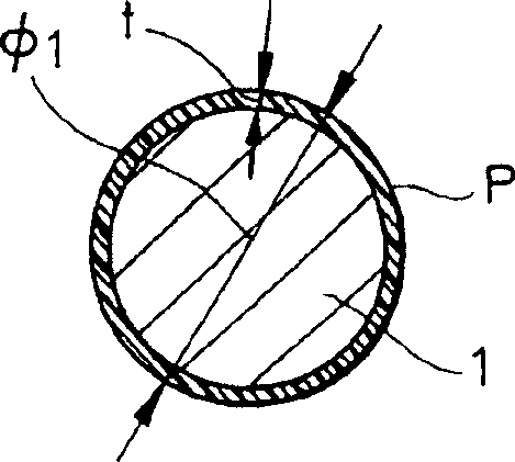
[0037] Fig. 1 has shown the perspective view of the first embodiment that is used for electric wire painting device of the present invention; figure 2 An enlarged cross-sectional view showing a state in which the varnish is applied to the outer surface of the electric wire by the dripping of the varnish from the dripping nozzle of the dripping device of the first embodiment; image 3 An enlarged sectional view showing a state of a typical electric wire forming a varnish insulating layer; and FIG. 4 showing a perspective view of a second embodiment of the apparatus for varnishing an electric wire of the present invention.
[0038] In Figure 1 to image 3 In , the reference number 1 represents - a wire moving at the desired speed. In this embodiment, said wire 1 has a circular cross-section and a diameter of 0.01 mm to 3.00 mm, preferably a diameter of 0.2 mm to 2.50 mm. The electric wire 1 is made of metal such as aluminum or its alloys, or iron, gold or other conductors, whi...
specific Embodiment 1
[0077] The electric wire having an outer diameter φ of 1.00 mm is fed by the rolling of the conveying roller (not shown), and the electric wire is taken up by the take-up roller (not shown), and the electric wire moves at a speed of about 20 m / min. By turning the working handle 12 of the dropping device 8 , the storage tank 15 is filled with a suitable amount of varnish W to drop drop by drop from the dropping nozzle 11 onto the electric wire 1 moving along the moving direction A.
[0078] In this embodiment, the varnish W is composed of a resin component and a solvent, the resin component is polyamide resin, epoxy resin, polyimide resin, etc., or a compound of two resins, and the solvent is cresol, xylene, ( Mixed) xylene, ethylbenzene, phenol, methanol, ethanol, water, etc. In this embodiment, the varnish W is composed of 10-30% by weight of the resin component and 70-90% by weight of the solvent. In this embodiment, when the liquid temperature of the varnish is 20°C-30°C, ...
Embodiment approach 2
[0084] Figure 4 shows a second embodiment of the device for applying varnish to electrical wires according to the invention. In FIG. 4 , like reference numerals refer to like elements in FIG. 1 . In the present embodiment, an insulating layer P of varnish W is formed on the outer surfaces of a plurality of electric wires 1, 1, . . . which are arranged to be movable at a predetermined speed. The device comprises, arranged at a lower position in the direction of movement of the arrow A, a trough-shaped container 2, 2, ... for the individual wires, and a dripping device on said container 2, 2, ... 8, 8, ... to correspond to the plurality of electric wires 1, 1, ... and for dripping and applying a predetermined amount of varnish on the outer surface of each of the plurality of electric wires 1, 1, ... W, and dripping devices 8, 8, . . . each provided with a flow rate adjusting portion 9. Each of the plurality of wires 1, 1, . . . has an outer diameter of 0.01 mm-3.00 mm, prefera...
PUM
| Property | Measurement | Unit |
|---|---|---|
| diameter | aaaaa | aaaaa |
| diameter | aaaaa | aaaaa |
| diameter | aaaaa | aaaaa |
Abstract
Description
Claims
Application Information