Sensorless motor driving device and its driving method

A motor drive and sensor technology, which is applied in the deceleration device of DC motor, starting device, AC motor control and other directions, can solve the problems of difficulty, difficulty in shortening time, and difficulty in starting sensorless motors quickly and reliably, and achieves rapid and reliable starting. Effect

Inactive Publication Date: 2005-02-09
コラボイノベーションズインコーポレイテッド
View PDF2 Cites 35 Cited by
  • Summary
  • Abstract
  • Description
  • Claims
  • Application Information

AI Technical Summary

Problems solved by technology

It is difficult to shorten the above predetermined time, because the reliability of starting will be affected when the zero crossing point cannot be accurately detected
On the other hand, the forced commutation control is difficult to shorten the time required from the start of the sensorless motor until the rotor speed reaches a stable value
Therefore, it is difficult for conventional sensorless motor drives to switch from forced commutation control to self-commutation control quickly and reliably when starting a sensorless motor
This makes it difficult to start sensorless motors quickly and reliably

Method used


Image

  • Sensorless motor driving device and its driving method
  • Sensorless motor driving device and its driving method
  • Sensorless motor driving device and its driving method

Examples


Embodiment 1

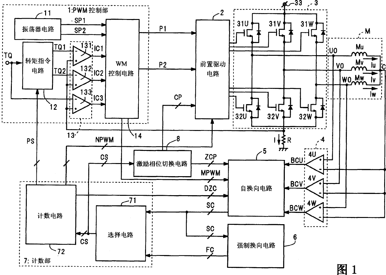
[0142] Fig. 1 shows a block diagram of a sensorless motor driving apparatus according to Embodiment 1 of the present invention. This sensorless motor driving device can be used to drive a sensorless motor M of three phases (U, V and W phases). The sensorless motor M is, for example, composed of three Y-connected motor coils Mu, Mv and Mw, three drive terminals UO, VO and WO, and one center tap C of the motor coils. The sensorless motor driving device according to Embodiment 1 of the present invention includes a PWM control unit 1, a pre-drive circuit 2, an output circuit 3, a BEMF comparison unit 4, a self-commutation circuit 5, a forced commutation circuit 6, a counting unit 7, and An excitation phase switching circuit 8 .

[0143] The output circuit 3 connects three sets of two power transistors connected in series in parallel between a power supply terminal 33 and a ground terminal that maintain a constant high voltage. The six power transistors are preferably MOSFETs, or...

Embodiment 2

[0217] The sensorless motor driving device according to Embodiment 2 of the present invention can be used to drive a sensorless motor having three phases (U, V, and W phases) in a manner similar to the driving device of Embodiment 1 described above. Except for the counting circuit 72, the components of this sensorless motor driving device are similar to those of the driving device of the above-mentioned Embodiment 1 in FIG. 1 . For similar components, reference is made to the above description of the first embodiment and to the drawings.

[0218] The internal counting circuit 72 of the sensorless driving device according to Embodiment 2 of the present invention has a different structure from that of the driving device of Embodiment 1 above. FIG. 19 is a block diagram showing the internal structure of the counting circuit 72 in the sensorless motor drive device according to Embodiment 2 of the present invention. FIG. 20 shows a timing diagram of the commutation signal CS, the ...

Embodiment 3

[0225] The sensorless motor driving apparatus according to Embodiment 3 of the present invention can be used to drive a sensorless motor having three phases (U, V, and W phases) in a manner similar to the driving apparatus of Embodiment 1 described above. Except for the forced commutation circuit 6, the components of this sensorless motor driving device are similar to those of the driving device of the above-mentioned embodiment 1 in FIG. 1 . For similar components, reference is made to the above description of the first embodiment and to the drawings.

[0226] According to the sensorless driving device of Embodiment 3 of the present invention, its internal forced commutation circuit 6 has a different structure from that of the driving device of Embodiment 1 above. Fig. 21 is a block diagram showing the internal structure of the forced commutation circuit 6 in the sensorless motor driving device according to the third embodiment of the present invention. In FIG. 21 , componen...


PUM


Abstract

Sensorless motor driving device and its driving method. A PWM control section (1) gently changes phase currents (Iu, Iv, and Iw) under a current driving control over a pre-drive circuit (2) and an output circuit (3). The pre-drive circuit (2) suspends energizing of the specific motor coil (Mu, Mv, and Mw) according to a PWM disable signal (NPWM) at PWM disable periods. A self-commutation circuit (5) performs zero crossing detection according to a BEMF detection signal (DZC) during BEMF detection periods. A count section (7) selects either a self-commutation signal (SC) or a forced commutation signal (FC) as a commutation signal (CS), whichever enters earlier, and, based on its intervals, generates the PWM disable signal (NPWM) and the BEMF detection signal (DZC). The BEMF detection period starts after the start of the PWM disable period, and finishes together with the PWM disable period at the switching of the energization phases.

Description

technical field [0001] The present invention relates to a device and method for driving a sensorless motor, in particular to a device and method for controlling the state of a sensorless motor under forced commutation control. Background technique [0002] In brushless motors, electrical commutation is used instead of mechanical commutation with brushes. Electrical commutation has requirements on the rotor position, that is, the rotation angle of the rotor. Conventional brushless motors are equipped with position sensors such as Hall devices and are used to detect rotor position. For example, see Japanese Patent Application Publication Nos. 2003-174789 and 2003-244983. [0003] In a sensorless motor, the voltage induced in the motor coil during rotor rotation is detected. This voltage is hereinafter referred to as BEMF (Back Electromotive Force). Detection of rotor position using BEMF is performed without a position sensor. Since a sensorless motor has no position senso...

Claims


Application Information

Patent Timeline
Patent Type & Authority Applications(China)
IPC IPC(8): H02P27/08H02P3/08H02P5/00H02P6/08H02P6/18H02P6/20H02P7/00
CPCH02P6/182
Inventor 岩永太志山本泰永西野英树
Owner コラボイノベーションズインコーポレイテッド
Why Eureka
Try Eureka