DC power supply system grounded fault detecting method and circuit

A DC power system, ground fault technology, applied in the fault location, measurement power, measurement device and other directions, can solve problems such as poor accuracy and accuracy, and achieve improved detection accuracy and accuracy, high detection accuracy and accuracy, and implementation of simple effect

Inactive Publication Date: 2005-02-23
SHANDONG UNIV
View PDF0 Cites 25 Cited by
  • Summary
  • Abstract
  • Description
  • Claims
  • Application Information

AI Technical Summary

Problems solved by technology

[0003] The present invention aims at the deficiencies of poor precision and accuracy of the existing DC power system ground fault detection method, and provides a DC power system ground fault detection method with high precision and accuracy and a detection circuit thereof

Method used


Image

  • DC power supply system grounded fault detecting method and circuit
  • DC power supply system grounded fault detecting method and circuit
  • DC power supply system grounded fault detecting method and circuit

Examples


Embodiment

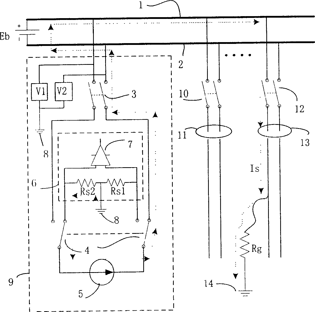
[0015] Example: in figure 1 In the given circuit schematic diagram, the DC power supply system is composed of DC power supply Eb, positive DC bus 1, negative DC bus 2, each branch and branch circuit breakers 10, 12, etc. The DC power supply Eb supplies DC power to each branch through the positive DC bus 1, the negative DC bus 2 and the branch circuit breakers 10 and 12, and the positive and negative buses 1 and 2 pass through the circuit breakers 10 and 12 and pass through the Hall current of each branch at the same time Transformers 11, 13. In the core circuit 9 of the present invention, the positive and negative busbars 1 and 2 are connected to the passive constant current circuit 5 and the current detection resistors Rs1 and Rs2 via the switch 3 and the switch 4 . The current value of the constant current circuit 5 can be detected by using the differential operational amplifier 7 to detect the voltage drop on the resistors Rs1 and Rs2. V1 and V2 are used to detect the vol...


PUM


Abstract

A method for detecting out fault point of earthing for DC power includes adding passive constant current circuit between nonearthing bus and earthing, measuring voltage value of bus to earthing and current value on each subcircuit calculating out insulation resistance value based on specific value of the two for confirming earthing subcircuit, using portable Hall mutual inductor to find out fault point along the subcircuit. A detection circuit of the method is also disclosed.

Description

(1) Technical field [0001] The invention relates to a grounding fault detection method for a DC power supply system, which is suitable for on-line detection and positioning of the insulation and grounding faults of the DC power supply system adopted by relay protection or control devices in power system substations, power plants, and factories and mines. (2) Background technology [0002] At present, the ground fault detection methods of DC power system can be technically divided into two categories: AC method and DC method. The AC method generally injects a low-frequency current signal into the grounding bus through a low-frequency signal generator, and then uses the signal receiver to receive the AC current amplitude or phase in each power supply branch to judge the grounding branch. With the complexity of the DC power supply system and the extensive use of digital protection and control devices, the distributed capacitance and filter capacitance of the system increase sha...

Claims


Application Information

Patent Timeline
Patent Type & Authority Applications(China)
IPC IPC(8): G01R31/02G01R31/08
Inventor 王广柱
Owner SHANDONG UNIV
Why Eureka
Try Eureka