Optical fiber vibrative sensor based on optical fiber raster

A fiber grating and micro-vibration technology, which is applied in vibration testing, machine/structural component testing, measuring devices, etc., can solve problems such as the inability to measure resonance frequency and affect the accuracy of sensors, and achieve low cost and simple production.

Inactive Publication Date: 2005-03-02
SHANGHAI JIAO TONG UNIV
View PDF2 Cites 25 Cited by
  • Summary
  • Abstract
  • Description
  • Claims
  • Application Information

AI Technical Summary

Problems solved by technology

This method has a high resolution and has the function of real-time online detection, but the disadvantage is that the resonance frequency cannot be measured. It can only be measur

Method used


Image

  • Optical fiber vibrative sensor based on optical fiber raster
  • Optical fiber vibrative sensor based on optical fiber raster

Examples


Embodiment Construction

[0021] The technical solution of the present invention will be further described below in conjunction with the accompanying drawings.

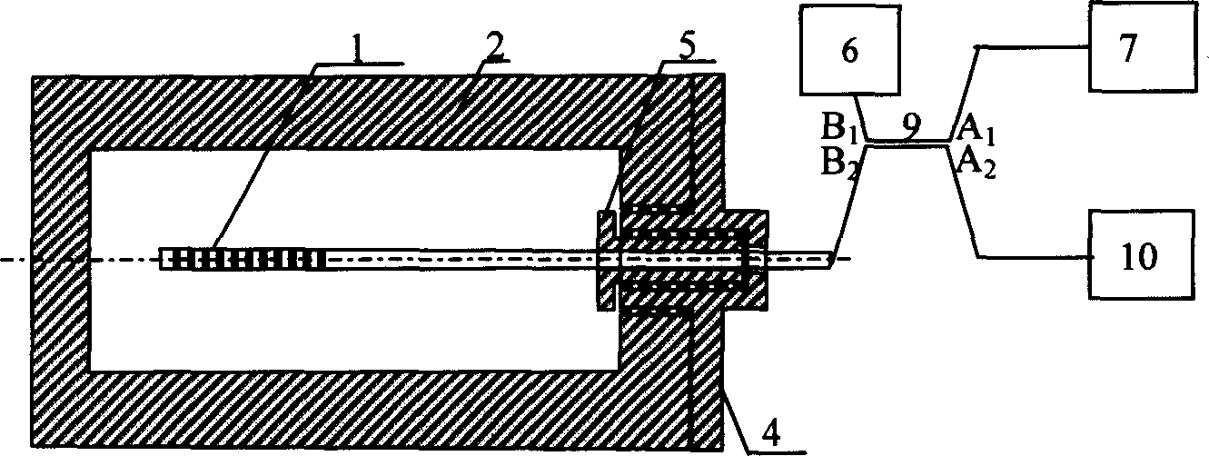
[0022] A structure of the optical fiber micro-vibration sensor of the present invention is as follows: figure 1 , including suspended fiber Bragg grating 1, insulating cylinder 2, calibrated fiber Bragg grating 3, connector 4, connector head 5, matching liquid 6, broadband light source 7, 2×2 coupler 9, spectrum analyzer 8 and transmission fiber Wait. Connection mode of the present invention: A of 2×2 coupler 9 1 The port is connected to the broadband light source 7, A 2 The port is connected with the spectrum analyzer 8, B 1 The port is connected with matching liquid 6, B 2 The port is connected to the transmission fiber.

[0023] One end of the hollow insulating cylinder 2 is screwed to the connector 4, the transmission optical fiber enters the insulating cylinder 2 through the connector 4, and is fixed at the center of the insulating c...


PUM


Abstract

A optical fiber microvibration sensor based on optical fiber raster, uses resonance of suspended Prague optical fiber raster and subject to be measured to magnify vibration amplitude of the object to be measured, and it can do wavelength type modulation or intensity type modulation measurement of light. Two contacts on one end of 2x2 coupler are separately linked to wide - band light source, spectrum analyzer or, and two contacts on another end to matching fluid and transmission optical fiber which crosses contacts to enter insulating cylinder and with one end charactered suspended Prague optical fiber raster in the wavelength type modulation its fixed in the center by union joint. In the structure of using spectrum analyzer for wavelength type modulation measurement, suspended Prague optical fiber raster for calibrating reflected light central wavelength of vibration equilibrium position is charactered on transmission optical fiber near inlet of the connector. The invention has solved the problem of optical fiber raster cross sensitivity, measuring microvibration of large instrument in circumstance of strong electromagnetic field and high voltage.

Description

technical field [0001] The invention relates to an optical fiber micro-vibration sensor based on a fiber grating, which is mainly used for measuring the micro-vibration displacement and micro-vibration velocity of a measured object, and belongs to the field of optoelectronic testing. Background technique [0002] Large instruments will vibrate slightly when they are working. Under normal circumstances, the amplitude of this vibration will not exceed a certain range. When the instrument works abnormally, the vibration will also be abnormal. In many cases, people hope to know the specific size of this vibration, so as to obtain the critical value of abnormal vibration, and take measures to rule out major accidents of equipment such as instruments, flight or operation. [0003] In many occasions, it is required that the micro-vibration measurement sensor probe cannot be charged and can work in the environment of electromagnetic interference. Some requirements must be online det...

Claims


Application Information

Patent Timeline
IPC IPC(8): G01M7/02
Inventor 黄云刚殷宗敏
Owner SHANGHAI JIAO TONG UNIV
Why Eureka
Try Eureka