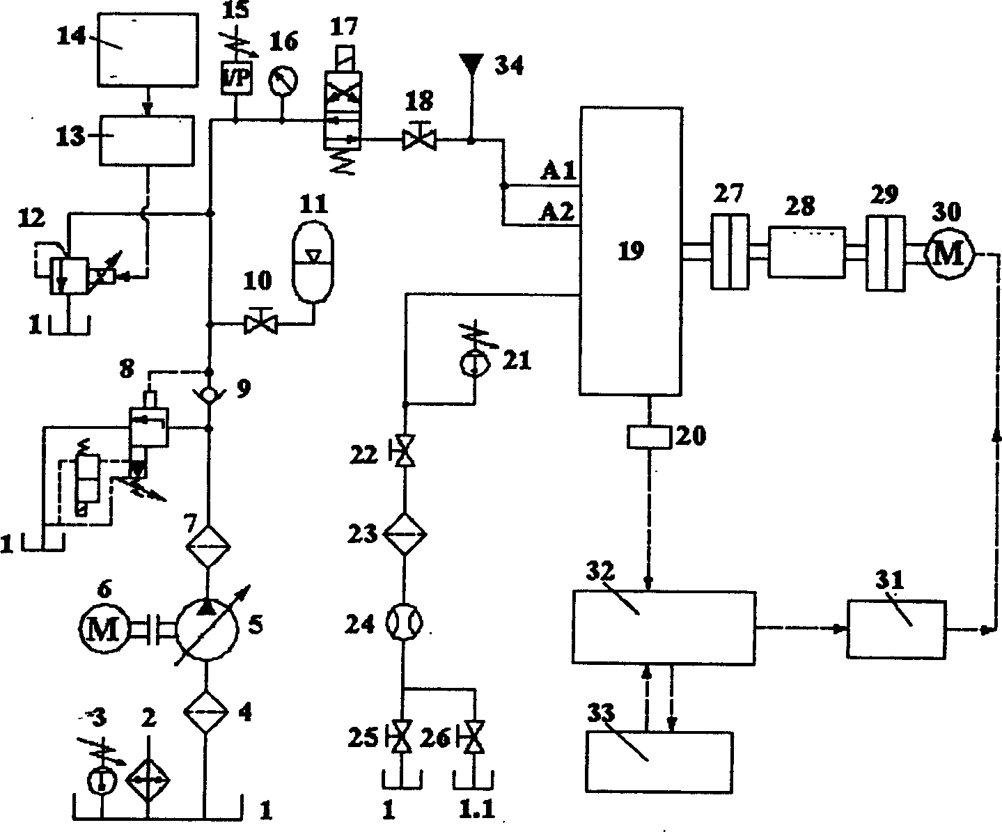
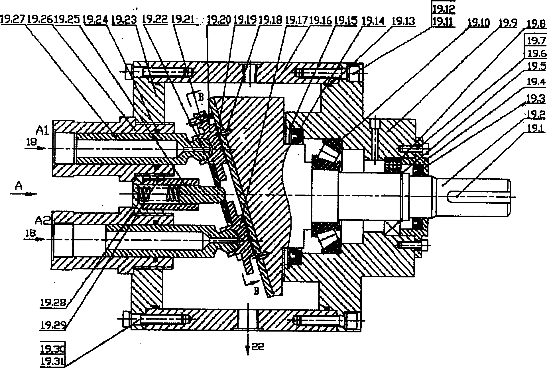
[0025] Such as figure 1 , figure 2 As shown, the present invention includes a hydraulic power system, a lubricating film test platform, and a monitoring and control system, in which:
[0026] 1) The hydraulic power system includes: a manual variable plunger pump 5 is connected to a fuel tank 1 equipped with a heater 2 and a temperature sensor 3 through an oil suction filter 4, a three-phase asynchronous motor 6 is connected to a manual variable plunger pump 5 through a coupling, The high-pressure oil port of the manual variable plunger pump 5 is connected to the oil inlets of the electromagnetic unloading relief valve 8 and the one-way valve 9 through the precision pressure filter 7, and the accumulator 11 is connected to the single valve through the first high-pressure stop valve 10. The oil outlet of the valve 9, the proportional relief valve 12 and the oil inlet of the two-position four-way electromagnetic reversing valve 17 are connected. The signal line of the signal generator 14 is connected to the proportional solenoid of the proportional relief valve 12 through the amplifier 13, The inlet of the two-position four-way solenoid valve 17 is equipped with a pressure sensor 15 and a precision pressure gauge 16, and the outlet port of the two-position four-way solenoid valve 17 is connected to the pure water hydraulic source through the second high-pressure stop valve 18. 34 is connected to the A1 and A2 ports of the sliding shoe pair lubrication characteristic movement device 19, and the leakage port of the sliding shoe pair lubrication characteristic movement device 19 is connected to the miniature temperature sensor 21, and is connected to the first low pressure stop valve 22 and the precision return oil filter in turn 23. After the flow sensor 24 is connected, it is divided into two paths, which are respectively connected with the second low-pressure shut-off valve 25, the oil tank 1 and the third low-pressure shut-off valve 26, and the water tank 1.1;
[0027] 2) The lubrication film test platform includes: the variable frequency speed regulating motor 30 is connected to the swash plate shaft 19.2 of the sliding shoe pair lubrication characteristic movement device 19 through the coupling 29, the torque speed sensor 28, and the coupling 27. The control line is connected with the variable frequency speed regulating motor 30;
[0028] 3) The monitoring and control system includes: the temperature sensor 3 is installed on the oil tank 1, the three micro-displacement sensors 20 are installed on the sliding shoe 19.20 in the sliding shoe pair lubrication characteristic movement device 19, and the torque and speed sensor 28 is connected to the variable frequency speed control motor 30 Between the sliding shoe pair lubrication characteristic movement device 19, the data lines of all sensors are connected to the terminal board of the data acquisition card 32. The data acquisition card 32 is installed on the main board of the industrial computer 33. The industrial computer 33 controls the data acquisition card 32 to output simulation The quantity signal controls the frequency converter 31.
[0029] Such as figure 2 , image 3 , Figure 4 , Figure 5 , Figure 6 As shown, the sliding shoe pair lubrication characteristic movement device 19 includes: the left end cover 19.23 is fixed by a screw 19.30, a spring washer 19.31 and the housing 19.16, the plunger sleeve 19.26 is fixed on the left end cover 19.23 by a thread, and the two plungers 19.27 are respectively Placed in the respective plunger sleeve 19.26, the hole is embedded between the plunger 19.27 and the plunger sleeve 19.26 with a stepped ring 19.24, the mandrel sleeve 19.29 is fixed on the left end cap 19.23 by threads, and the spring 19.28 is tightened in the mandrel sleeve 19.29 Push rod 19.25, push rod 19.25 in the middle of pressure plate 19.22, pressure plate 19.22 presses the first shoe 19.20 and second shoe 19.17 respectively on the thrust plate 19.19, the two shoes 19.20 and plunger 19.27 are pressed by the ball head rolling Package connection, three micro-displacement sensors 19.21 (ie figure 1 The micro-displacement sensor 20) is installed on the top and both sides of the first shoe 19.20 through a thread of 90°, the thrust plate 19.19 is fixed on the swash plate shaft 19.2 through the positioning pin 19.18, and the centripetal mounted on the swash plate shaft 19.2 Ball bearing 19.8, tapered roller bearing 19.10 and right end cover 19.9 hole tightly fit, skeleton type oil seal 19.14 is installed in the right end cover 19.9 hole, elastic retaining ring 19.15 fixes the position of the first skeleton type oil seal 19.14, right end cover 19.9 is screwed 19.11 It is fixed with spring washer 19.12 and housing 19.16, O-ring 19.13 is installed between the right end cover 19.9 and housing 19.16, the elastic retaining ring 19.5 is clamped in the position where the radial ball bearing 19.8 is fixed on the swash plate shaft 19.2, the cover plate 19.4 is fixed on the right end cover 19.9 by screws 19.6, spring washer 19.7, and the second skeleton oil seal 19.3 is fixed on the inner hole of the cover plate 19.4. The pressure piece 19.32 is fixed on the shoe 19.20 by the screw 19.36, the pressure piece 19.33 is fixed on the pressure plate 19.22 by the screw 19.36, the pressure piece 19.34 is fixed on the sliding shoe 19.20 by the screw 19.36, and the pressure piece 19.35 is fixed on the pressure plate 19.22 by the screw 19.36. Use Lei to compress the cable to seal 19.39, the miniature temperature sensor 19.37 (ie figure 1 The miniature temperature sensor 21) is fixed on the left end cover 19.23 by threads, the O-ring 19.38 is placed between the miniature temperature sensor 19.37 and the left end cover 19.23, the compression bolt 19.41 and the compression bolt 19.43 are respectively passed through the left compression ring 19.40 And the right compression ring 19.42 compresses the cable seal 19.39.
[0030] The hydraulic power system provides a high-pressure oil source for the lubricating film test platform. A three-phase asynchronous motor 6 drives a manual variable plunger pump 5 in the hydraulic oil circuit to provide a high-pressure oil source for the system. The high-pressure oil provided by the manual variable plunger pump 5 passes into the A1 and A2 ports of the left end cover 19.23. When testing different shoe pairs 19.20, the manual variable plunger pump 5 can be adjusted to meet the requirements of the leakage flow required by different shoe pairs. Adjusting the proportional relief valve 12 can change the outlet pressure of the manual variable plunger pump 5, and the pressure adjustment range is 0-34 MPa. When testing the sliding shoe pair of the oil hydraulic plunger pump, open the high-pressure cut-off valve 18, low-pressure cut-off valve 22, and low-pressure cut-off valve 25, and close the low-pressure cut-off valve 26; when testing the sliding shoe pair of the water hydraulic plunger pump, turn on Pure water hydraulic pressure source 34, close high-pressure cut-off valve 18 and low-pressure cut-off valve 25, and open low-pressure cut-off valve 26.
[0031] In the lubrication film test platform, the variable frequency speed-regulating motor 30 drives the sliding shoe pair lubrication characteristic movement device 19 through the coupling 29 to perform the lubrication characteristic test.
[0032] The pressure sensor 15 in the monitoring control system measures the pressure of the system, and the micro-displacement sensor 20 measures the lubricating film thickness of the sliding shoe pair under different working conditions. The flow sensor 24 measures the leakage flow of the shoe pair. The torque and rotation speed sensor 28 measures the torque and rotation speed output by the variable frequency speed control motor 30. The temperature sensor 3 measures the temperature of the fuel tank 1. The micro temperature sensor 21 measures the temperature of the liquid between the shoe pairs. The measured experimental data are all transferred to the industrial computer 33 through the data acquisition card 32. At the same time, the industrial computer 33 also performs feedback control on the frequency converter 31 through the data acquisition card 32.
[0033] The motor drives the main shaft 19.2, and the main shaft 19.2 drives the thrust plate 19.19 to rotate at high speed. The high-pressure liquid flows in from A1 and A2 of the sliding shoe pair lubrication characteristic movement device 19, and leaks out from the inner and outer sealing belts through the sliding shoe pair. The leakage flow can be measured by the flow sensor 24.
[0034] In the experiment, the eddy current micro-displacement sensor is used to directly measure the lubricating film thickness of the sliding shoe pair. The installation position of the three micro displacement sensors 19.21 is as follows Figure 4 As shown, a plane can be determined according to the values measured by three micro-displacement sensors, which can obtain the value of the lubricating film thickness and the shape of the lubricating film of the sliding shoe pair.
[0035] Because the high-speed relative rotational movement of the shoe pair generates a lot of shear heat, the temperature of the liquid between the shoe pair rises faster than the liquid in the device cavity, and the viscosity-temperature is the key factor leading to the formation of the sliding shoe pair lubricating film One, so it is very important to measure the temperature of the fluid in the shoe pair gap. The miniature temperature sensor 19.37 is used to measure the temperature of the fluid between the shoe pairs, such as Figure 5 Shown. Therefore, the influence of fluid viscosity-temperature on the lubricating film of the sliding shoe pair can be investigated in the experiment.
[0036] Slipper pair lubrication characteristics The parts in the movement device 19 are all made of stainless steel, such as figure 2 As shown, the test device can screen the friction pairs of various materials under various mineral oil media and water media. Especially the lubrication mechanism and wear mechanism of new engineering materials can be studied in water environment and under high pressure and high speed conditions, so as to determine the best water hydraulic plunger pump shoe pair material pairing and structure.
[0037] Such as Figure 6 As shown, by tightening the compression bolt 19.41 from the left, the cable seal 19.39 can be compressed through the left compression ring 19.40, thereby sealing the cable outlets of the three micro-displacement sensors 19.21 of the sliding shoe pair lubrication characteristic motion device 19.