Boost type active interlaced parallel soft switch circuit

An active interleaving and boosting technology, which is applied in conversion equipment without intermediate conversion to AC, high-efficiency power electronic conversion, climate sustainability, etc. Efficiency, few additional components, simple structure effect

An active interleaving and boosting technology, which is applied in conversion equipment without intermediate conversion to AC, high-efficiency power electronic conversion, climate sustainability, etc. Efficiency, few additional components, simple structure effect

CN1588773AInactive Publication Date: 2005-03-02ZHEJIANG UNIV

Image

  • Boost type active interlaced parallel soft switch circuit

Examples


Embodiment Construction

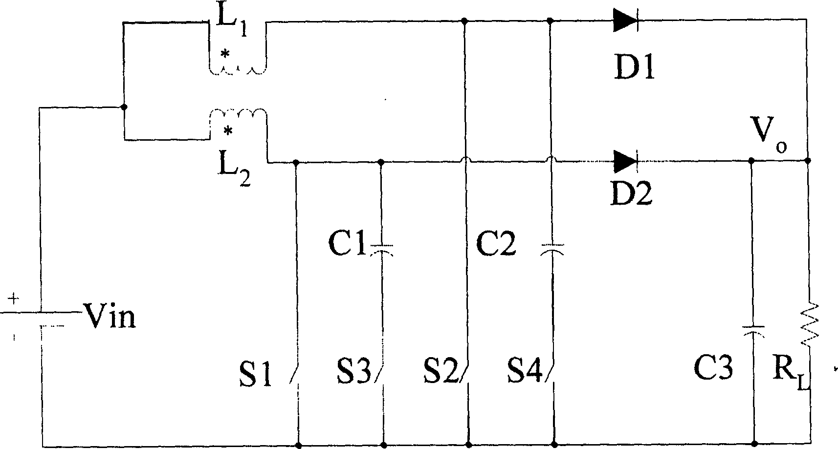
[0008] see figure 1 , the step-up active interleaved parallel soft switching circuit includes two coupled inductors L1, L2, two freewheeling diodes D1, D2, two power switch tubes S1, S2, the drain of the first power switch tube S1 and The anode of the second diode D2 is connected to one end of the second inductor L2, the drain of the second power switch tube S2 is connected to the anode of the first diode D1 and one end of the first inductor L1, and the other end of the first inductor L1 One end is connected to the other end of the second inductance L2, which is characterized in that the first power switch tube S1 is connected in parallel with a series circuit composed of the first capacitor C1 and the first auxiliary switch tube S3, wherein the first auxiliary switch tube S3 is connected to the first power switch tube S3 The switching tube S1 has the same direction, and the first capacitor C1 is connected to the junction of the first power switching tube S1 and the second ind...


PUM


Abstract

This invention relates to a voltage-boosting type active staggered parallel-connection soft switching circuit. It comprises: two phase coupled inductors, two follows current diodes, two power switching tubes. The drain electrode of the first power switching tube, the positive pole of the second diode and one end of the second inductor are connected. The drain electrode of the second power switching tube, the positive pole of the fist diode and one end of the first inductor are connected. The other end of the first inductor and second inductor are connected. The first power switching tube is paralllet connected with a series circuit composed of the first capacitor and the first auxiliary switching tube; while the second power switching tube is parallel connected with a series circuit composed of the second capacitor and the second auxiliary switching tube. Advantages are: less auxiliary devices, simple structure, no need of additional testing.

Description

technical field [0001] The present invention relates to DC-DC converters. Specifically, it is a step-up active interleaved parallel soft switching circuit. Background technique [0002] A conventional step-up (Boost) interleaved parallel DC-DC converter includes two inductors L1, L2, two freewheeling diodes D1, D2, two power switch tubes S1, S2, and the drain of the first power switch tube S1 The pole is connected with the anode of the second diode D2 and one end of the second inductor L2, the drain of the second power switch tube S2 is connected with the anode of the first diode D1 and one end of the first inductor L1, and the first inductor L1 The other end of is connected to the other end of the second inductor L2. This step-up interleaved parallel DC-DC converter generally works as a hard switch, and the switching loss is relatively large. In recent years, some soft switching circuits have been studied successively. There are two main types: one is to add active and p...

Claims


Application Information

Patent Timeline
02 Mar 2005
Publication
CN1588773A
IPC
H02M3/18
CPC
Y02B70/1491; Y02B70/10
Inventors
何湘宁; 姚刚