Pressure opening and closing valve

A technology of pressure switch and valve body, applied in the field of pressure switch valve, can solve the problems of beating, difficult to prevent noise, noise, etc.

Inactive Publication Date: 2005-03-09
NIFCO INC +1
View PDF1 Cites 5 Cited by
  • Summary
  • Abstract
  • Description
  • Claims
  • Application Information

AI Technical Summary

Problems solved by technology

[0005] In the above-mentioned existing pressure switching valve, between the inner peripheral surface of the housing containing the positive pressure valve body and the outer peripheral surface of the positive pressure valve body, turbulent flow will occur when the fluid flows in the positive pressure inside the tank, so that , the vibrating positive pressure valve body collides with the inner peripheral surface of the shell and generates noise
In addition, due to the influence of the vibration of the vehicle body, the positive pressure valve body in the casing jumps, which will also generate noise.
[0006] In order to prevent the occurrence of the above-mentioned noise, although it is conceivable to reduce the fitting gap between the two so that the positive pressure valve body does not jump in the housing, on the basis of ensuring the smooth movement of the positive pressure valve body, the gap is reduced to avoid It's a difficult thing to have this level of noise
That is, it is difficult to prevent the generation of noise while ensuring smooth operation of the conventional pressure switch valve.

Method used


Image

  • Pressure opening and closing valve
  • Pressure opening and closing valve
  • Pressure opening and closing valve

Examples


Embodiment 1

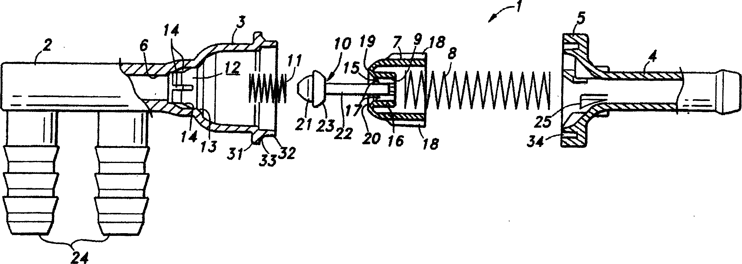
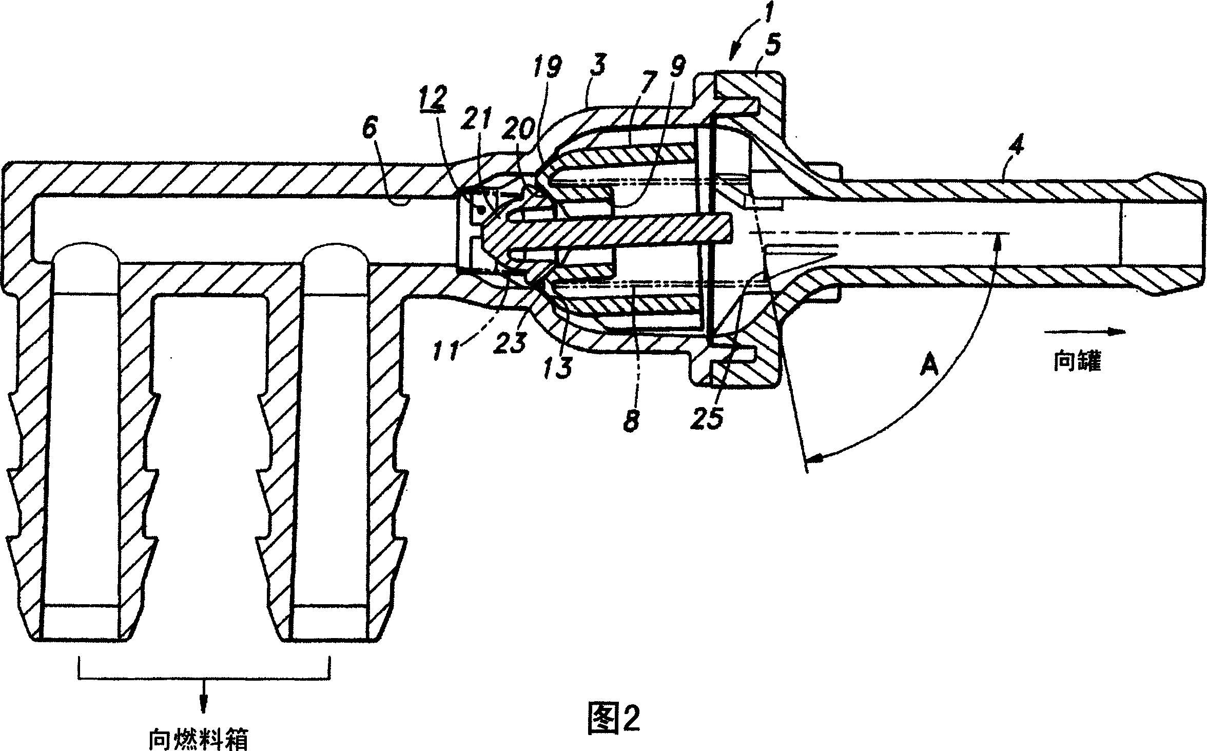
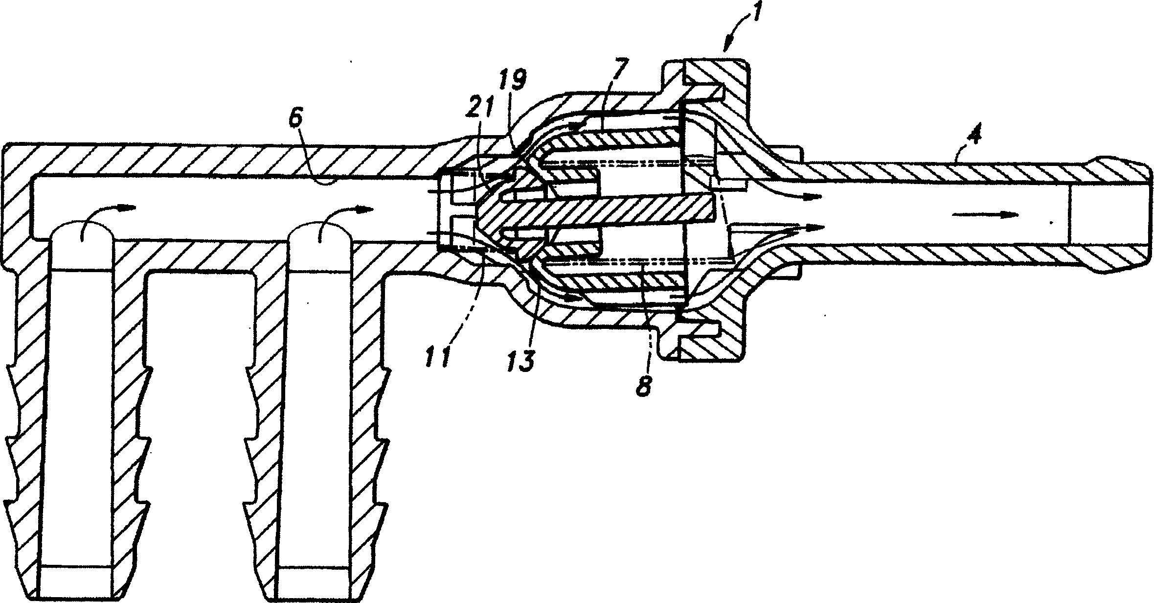
[0045] In the pressure switch valve 1 described above, the contact surface with the tip of the large-diameter coil spring 8 of the spring support portion (spring seat) 25 provided on the case cap 5 is arranged so as not to be perpendicular to the central axis of the case main portion 3 Intersect and set to a suitable inclination angle A. Therefore, the central axis of the large-diameter coil spring 8 in the natural state is not parallel to the central axis of the housing main part 3, that is, with respect to the axis of the positive pressure valve seat 13 formed in the central part of the housing main part, The central axis of the large-diameter coil spring 8 is inclined at an appropriate angle. Therefore, when the positive pressure valve body 7 is installed in the housing main part 3 while compressing the large diameter coil spring 8 , the elastic force direction of the large diameter coil spring 8 is not parallel to the axis of the positive pressure valve body 13 . That is,...

Embodiment 2

[0047] Figure 5 Another method for inclining the axis of the valve-opening elastic force applied to the positive pressure valve body 7 is shown. A coiled large diameter coil spring 26 with the axis inclined in the natural state is used. In this case, the centers of the positive pressure valve seat 13 and the spring support portion 25 are made to coincide with each other, and even if the contact surface with the tip of the large-diameter coil spring 26 of the spring support portion 25 is aligned with the center of the housing main portion 3 The shafts intersect perpendicularly, and when compressing the large-diameter coil spring 26 while installing it between the positive pressure valve body 7 and the spring support portion 25, because of the elastic force for opening the valve of the large-diameter coil spring 26 of the positive pressure valve body 7 The center of the valve seat 13 does not coincide with the center of the positive pressure valve seat 13, so the same effect a...


PUM


Abstract

To provide a pressure opening and shutting valve capable of controlling occurrence of beating noises without blocking smoothness of operation. The opening and shutting valve (1) comprises a housing (a housing body 3 and a housing cap 5) having first port (a fluid passage 6) and a second port (hose connecting nozzle 4), and a valve body (positive pressure valve body 7), which is housed in the housing, normally blocking the first port by urging with a spring (a coil spring 8 with a large diameter) and opening when differential pressure between the first port and the second port exceeds a designated value. An axis of urging force for closing a valve by means of the valve body is set to be non-parallel to an axis of a valve seat (a positive pressure valve seat 13) that brings into contact with the valve body.

Description

technical field [0001] The present invention relates to a pressure switching valve, the valve body is arranged in the pipeline, and the valve body is automatically opened and closed according to the pressure difference between the front and rear of the valve body. Range and set the pressure switch valve of the two-way valve between the fuel tank and the tank. Background technique [0002] In order to keep the pressure in the fuel tank of automobiles within a specified range, a pressure switch valve with two-way check function is provided between the fuel tank and the tank of the automobile. The pressure switch valve works like this: when the tank internal pressure rises during oil supply, it can detect the full tank state and close in two directions at the same time. When the temperature rises, etc., when the tank internal pressure exceeds the specified value, Open the valve in the direction that the evaporated gas on the tank is adsorbed to the tank, and open the valve in ...

Claims


Application Information

Patent Timeline
Patent Type & Authority Applications(China)
IPC IPC(8): B60K15/077F02M25/08F02M37/00F16K17/04F16K17/19F16K17/196
CPCY10T137/7777F16K17/196F02M25/0836B60K15/035F16K17/18F16K27/02F16K1/34
Inventor 佐藤广司
Owner NIFCO INC
Why Eureka
Try Eureka