
Digital controlled high-pressure micronizer

A micro-powder milling and high-pressure technology, applied in grain processing, etc., can solve the problems of difficult adjustment of grinding roller pressure, unqualified powder forming rate, easy wear of contact surface, etc., and achieves the effects of saving manpower, reducing working noise, and being easy to adjust

Inactive Publication Date: 2005-03-30
杨金国
View PDF0 Cites 7 Cited by
  • Summary
  • Abstract
  • Description
  • Claims
  • Application Information

AI Technical Summary

Problems solved by technology

[0003] The purpose of the present invention is to provide a numerically controlled high-pressure micropowder mill, which mainly solves the technical problems of unqualified pulverization rate and low fineness of existing mills, so as to achieve the effect of high yield and uniform fineness. Can be adjusted from 80 mesh to 6000 mesh
[0005] Another object of the present invention is to solve the technical problems in the prior art that one spring presses on several grinding roller parts at the same time, it is difficult to adjust the pressure of the grinding roller and the contact surface is easy to wear

Method used


Image

  • Digital controlled high-pressure micronizer
  • Digital controlled high-pressure micronizer

Examples


Embodiment Construction

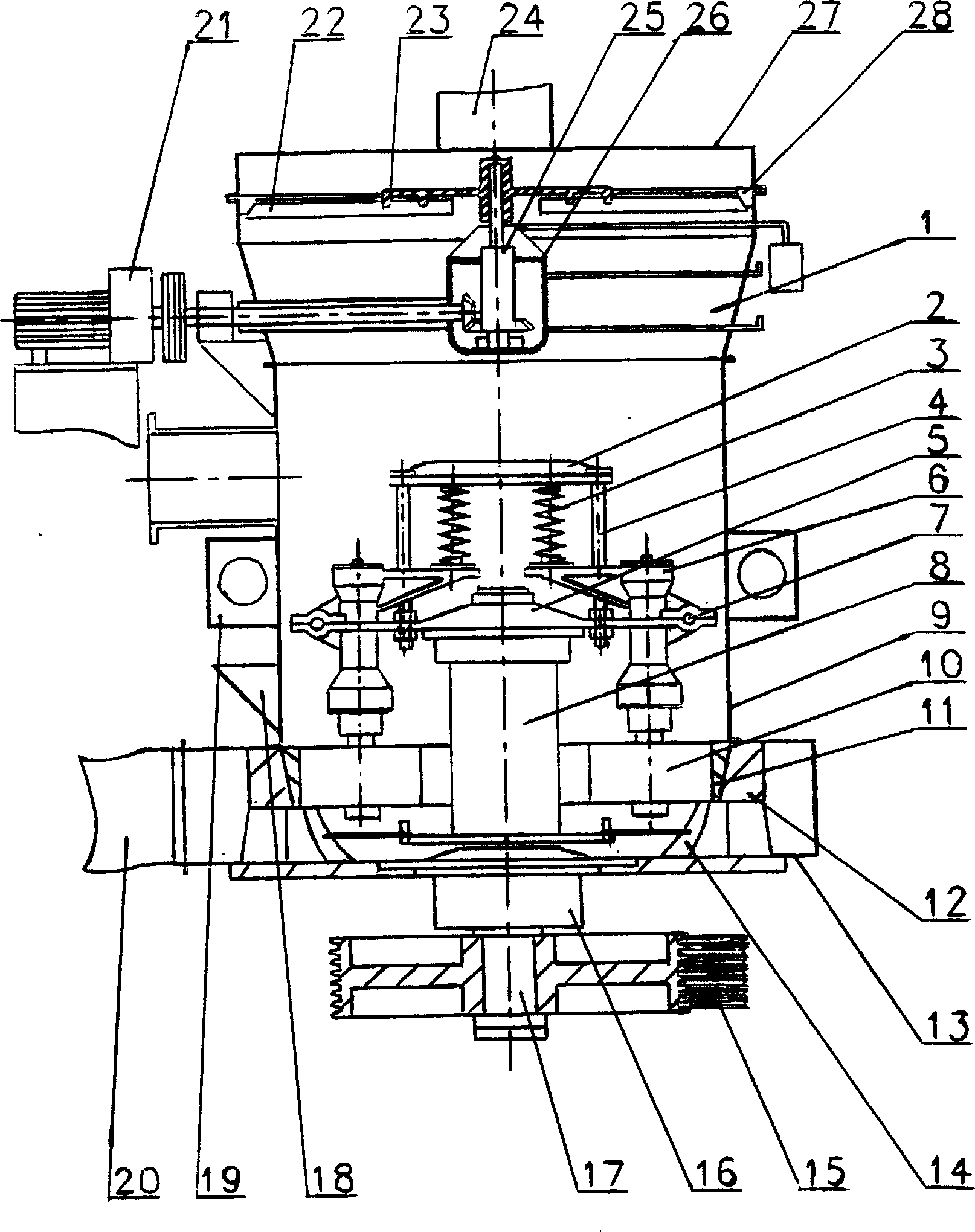
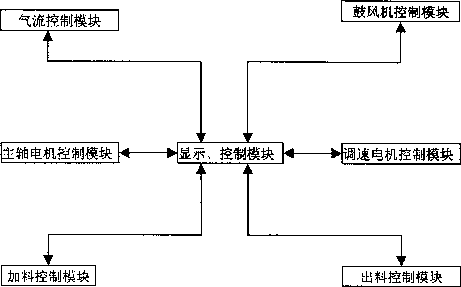
[0036] Combine below figure 1 , figure 2 The present invention is described in further detail:

[0037] Cover cylinder 9, grinding ring 11, air inlet volute 13, bearing seat 16 and feeding hopper 18 are respectively installed on the base 12 of CNC high-pressure micropowder mill, blade 14 is installed on blade frame 8, blade frame 8 It is connected with the grinding roller hanger 5 and is set on the main shaft 17 together. The grinding roller parts 6 are suspended on the grinding roller hanger 5 through the cross arm shaft 7, wherein each grinding roller part 6 is equipped with a spring 3, and the spring 3 is equipped with a spring pressure plate 2, and the spring pressure plate 2 is connected with the roller hanger 5 through the screw rod 4. The spring pressure plate 2 and the roller hanger 5 are connected and fixed through the screw rod 4 with nuts; in the middle of the cover tube 9, there is an air flow pressure reduction hole 19. A soft connection 20 is used between the...


PUM


Abstract

A numerally controlled high-pressure pulverizing for ore is composed of machine frame, cylindrical cover with air inlet volute, airflow pressure releasing hole and feeding hopper, grinding ring, mainshaft driven by motor, shovel and its holder, centrifugal grinding roller and its holder, and powder fineness analyzer.

Description

technical field [0001] The invention relates to a device for grinding ore by using a centrifugal force grinding roller, in particular a numerical control device suitable for grinding various brittle materials with a Mohs hardness below 9.3. Background technique [0002] In existing grinding equipment such as high-pressure grinding machines, some grinding rollers are rolled on the inner surface of the grinding ring under the action of centrifugal force, and some are rolled on the inner surface of the grinding ring under the action of spring pressure. between the rings and was crushed. Due to the poor effect of centrifugal force alone. In the mill, only a spring with a higher stiffness acts on several grinding roller parts simultaneously, which has the following disadvantages: the first, it is more difficult to rotate a nut compression spring to reach a pre-pressure of about 2000 kilograms. Second, due to the different particle sizes of the crushed materials, the grinding ro...

Claims


Application Information

Patent Timeline
Patent Type & Authority Applications(China)
IPC IPC(8): B02C15/00B02C15/04
Inventor 杨金国
Owner 杨金国
Learn More