

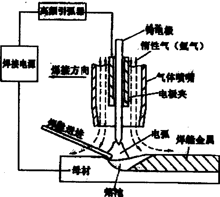
Dual tungsten electrodes welding torch in use for argon are welding
A tungsten argon arc and tungsten electrode technology, applied in arc welding equipment, electrode characteristics, welding equipment, etc.
- Summary
- Abstract
- Description
- Claims
- Application Information
AI Technical Summary
Problems solved by technology
Method used
Image

Examples
specific Embodiment approach 1
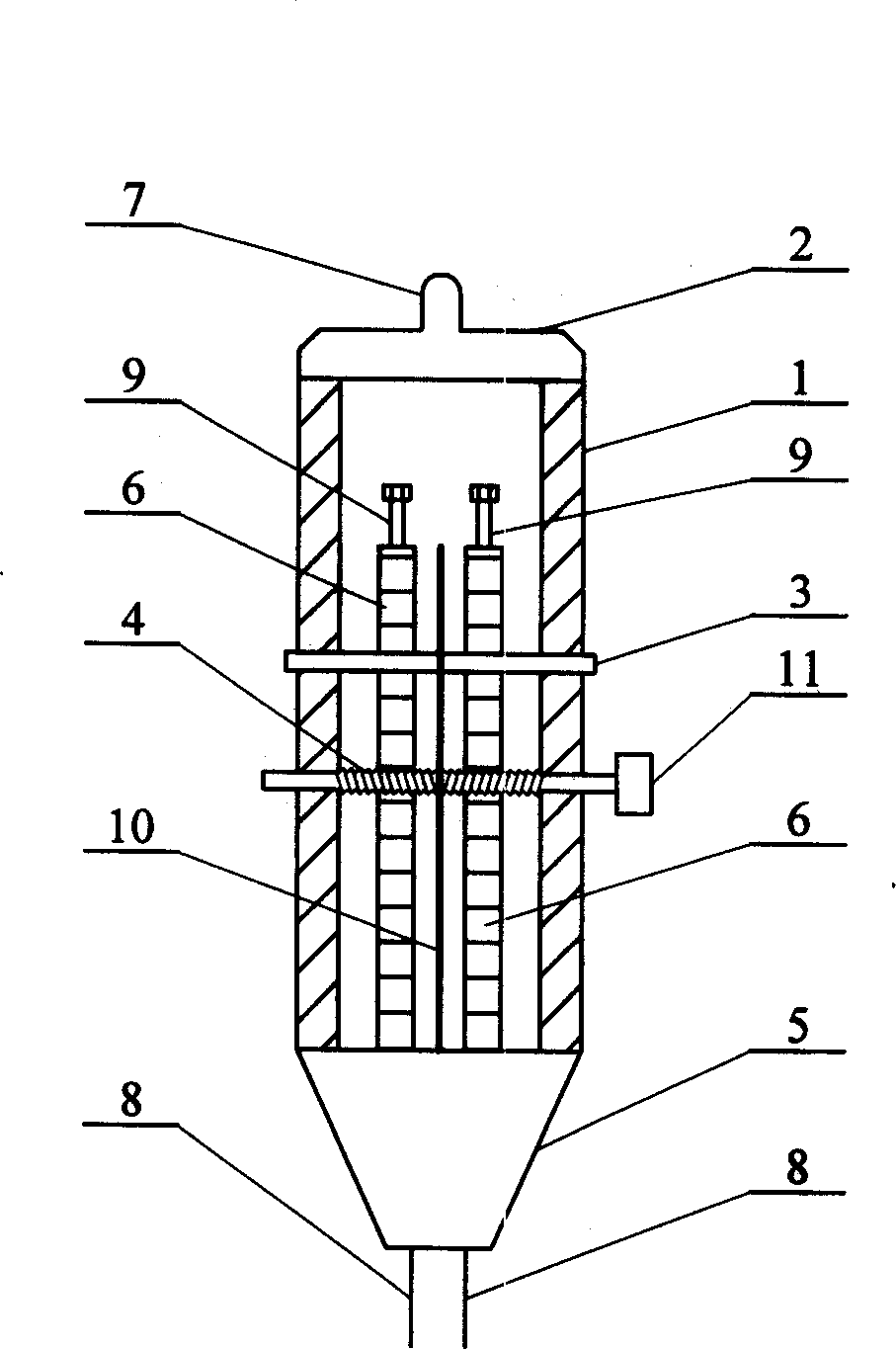
[0005] Specific implementation mode one: (see figure 2 ) This embodiment consists of a welding torch body 1, an air inlet cover 2, an air outlet cover 5, two conductors 6, two tungsten poles 8, two electric cable fastening bolts 9, and an insulating sheet 10; the air inlet cover 2 Fixed on the upper end of the torch body 1, the air inlet cover 2 is provided with an air inlet hole 7, the gas outlet cover 5 is fixed on the lower end of the torch body 1, and the upper ends of the two tungsten electrodes 8 are respectively fixed on the lower ends of the two conductors 6 , the two incoming cable fastening bolts 9 are respectively fixed on the upper ends of the two electric conductors 6, the two electric conductors 6 are arranged vertically and parallel in the torch body 1, and the lower ends of the two tungsten electrodes 8 are arranged at the lower end of the gas outlet cover 5 The insulating sheet 10 is arranged between the two conductors 6 in the torch body 1 .
specific Embodiment approach 2
[0006] Specific implementation mode two: (see figure 2 ) The difference between this embodiment and the specific embodiment one is that it increases the guide rod 3 and the distance adjustment screw 4, the guide rod 3 and the distance adjustment screw 4 are vertically arranged with the conductor 6 respectively, and the middle part of the guide rod 3 is arranged In the two conductors 6 and insulating sheet 10, the guide rod 3 is slidingly connected with the conductor 6, the two ends of the guide rod 3 are fixed on the outer wall of the welding torch body 1, and the middle part of the adjustable distance screw 4 is arranged on the conductor 6. And in the insulating sheet 10, the two ends of the distance-adjusting screw 4 are arranged on the outer wall of the welding torch body 1 on the lower side of the guide rod 3, and one side end of the distance-adjusting screw 4 is provided with a knob 11, and the distance-adjusting screw The bar 4 is threadedly connected with the two condu...
PUM
 Abstract
Description
Claims
Application Information