
Plasma production device and method and RF driver circuit

A plasma, plasma source technology, applied in the field of plasma generation systems, can solve the problems of low maintenance cost, increased complexity, etc., and achieve the effect of mitigating damage

Inactive Publication Date: 2005-03-30
PLASMA CONTROL SYST LLC
View PDF2 Cites 10 Cited by
  • Summary
  • Abstract
  • Description
  • Claims
  • Application Information

AI Technical Summary

Problems solved by technology

These matching networks add to the complexity of working with switch mode power supplies instead of omitting the dynamic matching network
[0013] Problems faced in efficient plasma generator design include the need for low maintenance and easily configurable antennas, the omission of expensive and limited matching networks that couple the RF power supply to the nonlinear dynamic impedance provided by the plasma , and effective RF power

Method used


Image

  • Plasma production device and method and RF driver circuit
  • Plasma production device and method and RF driver circuit
  • Plasma production device and method and RF driver circuit

Examples


Embodiment Construction

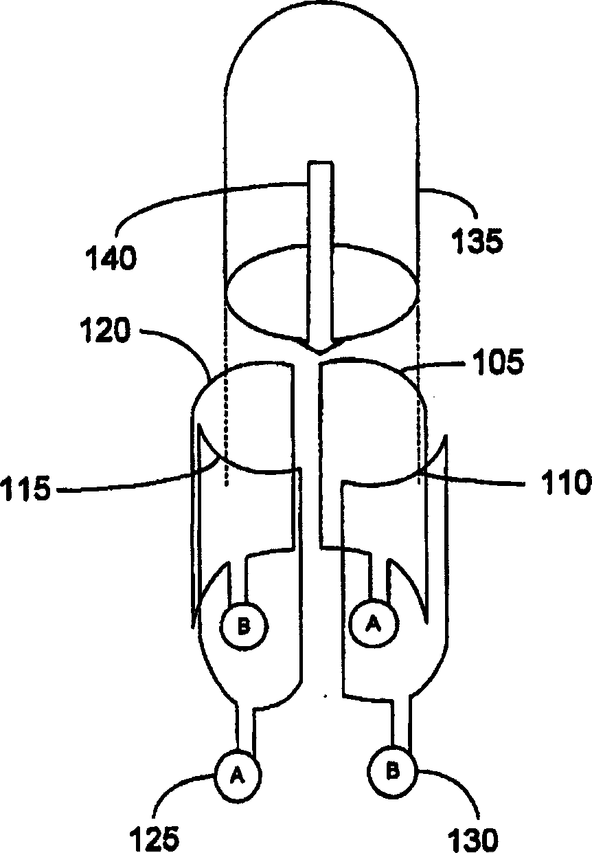
[0035] Referring first to the accompanying drawings, figure 1 A plasma source chamber with two sets of antenna elements configured in accordance with an embodiment of the invention is illustrated. The antenna design comprises two orthogonal single-turn or multi-turn loop elements 105, 110, 115 and 120, all arranged about a common axis. Each antenna element 105, 110, 115 and 120 is driven by an RF power source, either A 125 or B 130 as shown. Each antenna loop can be coupled to the same RF power supply with a phase splitter or to a specific RF power supply, or drive quadrature antenna elements. Preferably the loops in the antenna are constructed of eight (8) gauge polytetrafluoroethylene coated with wire (although copper wire or other conductors could also be used).

[0036] figure 1 Two sets of orthogonal two-element Helmholtz coiled loop antennas are illustrated, with loop elements 105 and 115 in one set and loop elements 110 and 120 in a second set. These ring elements a...


PUM

PropertyMeasurementUnit
lengthaaaaaaaaaa
lengthaaaaaaaaaa

Abstract

An RF driver circuit and an orthogonal antenna assembly / configuration, are disclosed as part of a method and system for generating high density plasma. The antenna assembly (105, 115, 110, 120) is an orthogonal antenna system that may be driven by any RF generator / circuitry (125, 130) with suitable impedance matching to present a low impedance. The disclosed RF driver circuit uses switching type amplifier elements and presents a low output impedance. The disclosed low-output impedance RF driver circuits eliminate the need for a matching circuit for interfacing with the inherent impedance variations associated with plasma. Also disclosed is the choice for capacitance or an inductance value to provide tuning for the RF plasma source.

Description

technical field [0001] The present invention generally relates to the design and implementation of plasma generation systems. More particularly, it relates to radio frequency amplifiers, antennas and effective circuit connections for interfering with the amplifiers and antennas to generate plasma. Background technique [0002] Plasma is generally considered the fourth state of matter, the others being solid, liquid and gas. In the plasma state, the basic constituents of matter are essentially in an ionized form that renders them useful in many fields because, among other factors, of their enhanced reactivity, energy, and suitability for forming directed beams. [0003] Plasma generators are commonly used in the manufacture of electronic components, integrated circuits, and medical devices, and in the work of various goods and machines. For example, plasmas are widely used to deposit layers of desired substances, such as after chemical reactions or sputtering from sources t...

Claims


Application Information

Patent Timeline
Patent Type & Authority Applications(China)
IPC IPC(8): C23F4/00H01J37/32H01L21/205H01L21/3065H01Q7/00H01Q21/20H05H1/46
CPCH01J37/32128H01Q7/00H01Q21/205H05H1/46H01J37/32174H01J37/32082H01J37/321H01J37/32522H01J37/32
Inventor J·D·埃文斯P·A·普日比尔
Owner PLASMA CONTROL SYST LLC
Learn More