Pressure regulating current stablizing valve

A technology of steady flow valve and pressure regulation, applied in safety valve, balance valve, valve device and other directions, can solve the problems of many components of pressure regulating equipment, small pressure regulating range, complex structure, etc., and achieve easy assembly and maintenance, and pressure regulating range Large, easy-to-use effect

Inactive Publication Date: 2005-04-13
乌鲁木齐科丰农业服务有限公司
View PDF0 Cites 4 Cited by
  • Summary
  • Abstract
  • Description
  • Claims
  • Application Information

AI Technical Summary

Problems solved by technology

[0013] The purpose of the present invention is to provide a pressure regulating and stabilizing valve, which can effectively solve the problems of the existing pressure regulating equipment with many components, complex structure, troublesome assembly, cumbersome process, small pressure regulating range and high cost

Method used


Image

  • Pressure regulating current stablizing valve
  • Pressure regulating current stablizing valve
  • Pressure regulating current stablizing valve

Examples


Embodiment Construction

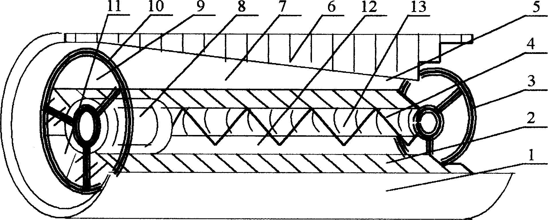
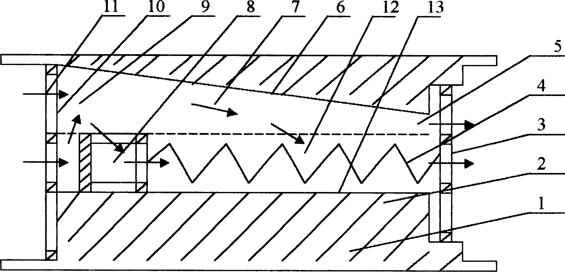
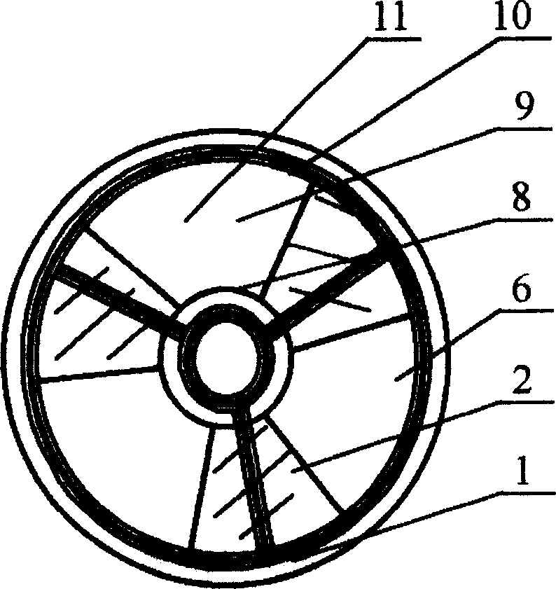
[0027] refer to figure 1 , figure 2 , image 3 with Figure 4 , the present invention is made up of valve body 1, spool 8, spring 4, spool retainer 10 and spring retainer 3, and valve body 1 is straight-through cylindrical, and its inner wall radially is three protruding walls 2 and three A concave wall 6, three convex walls 2 and three concave walls 6 are radially spaced to form an inner cavity 12 of the valve body 1, the inner cavity 12 surrounded by the three convex walls 2 is cylindrical, and the three concave walls 6 surround The formed inner cavity 12 is frustum-shaped or cylindrical; three convex walls 2 and three concave walls 6 axially form three overflow channels 7 that gradually shrink from the water inlet 9 to the water outlet 5; the three convex walls 2 and the Three recessed walls 6 radially surround the valve core 8 to form three flow-through sections 11. The areas of the three flow-through sections 11 gradually shrink as the valve core 8 moves from the wate...


PUM


Abstract

The pressure regulating and flow stabilizing valve consists of valve body, valve core, spring, valve core retaining sheet and spring retaining sheet. The valve body is straight cylinder and its inner wall has alternately arranged convex wall and concave wall to enclose the valve core to constitute flow area. The axial cross section is gradually reduced from the water inlet to the water outlet, and the inner spring has one end fixed to the valve core and the other end fixed to the spring retaining sheet. When the pressure in the upstream increases, the core compressing spring will move towards the water outlet to reduce the flow section and increase the pressure loss, and the pressure in the water outlet and the flow rate will be maintained constant. The valve core has long moving stroke, and this results in wide pressure regulating range. The present invention is simple.

Description

1. Technical field [0001] The invention is a pressure-regulating and flow-stabilizing valve, in particular a pressure-flow regulating device used for spraying and micro-infusion water distribution pipelines. 2. Background technology [0002] Modern agricultural water-saving irrigation technologies such as sprinkler irrigation and micro-irrigation are inseparable from the water transmission and distribution pipeline system, and the pressure-flow adjustment equipment is an important supporting equipment for the system. [0003] At present, in pipeline irrigation operations in my country, due to the lack of pressure-flow adjustment equipment, when the pressure at the inlet of the branch pipe of the pipeline system is too high and needs to be lowered appropriately, a "water resistance pipe" (ie The pipe diameter is smaller than that of the branch pipe) or the method of reducing the valve opening. Although these methods can adjust the pressure and flow, but when the upstream press...

Claims


Application Information

Patent Timeline
Patent Type & Authority Applications(China)
IPC IPC(8): F16K17/04G05D16/04
Inventor 刘林军李燕华
Owner 乌鲁木齐科丰农业服务有限公司
Why Eureka
Try Eureka