Mould clamping means for flastic bottle-blowing machine

A mold clamping mechanism and blow molding machine technology, applied in the field of plastic blow molding machines, can solve problems such as lack of booster pressure supplement, affecting product qualification rate, inconsistent operation, etc.

Inactive Publication Date: 2005-05-04
蔡桂森
View PDF0 Cites 13 Cited by
  • Summary
  • Abstract
  • Description
  • Claims
  • Application Information

AI Technical Summary

Problems solved by technology

One is that the mold clamping mechanism in the prior art can be divided into one-way mold clamping and two-way mold clamping. The one-way mold clamping is that one mold is installed on the fixed template, and the other mold is installed on the movable template, and a single cylinder is used for mold clamping. The entire itinerary is completed by the active template, so it takes a long time and the work efficiency is low
The two-way mold clamping is that two molds are respectively installed on two movable templates, and the two molds are closed or opened in opposite directions, and the action is relatively fast. , the other template relies on pulling, so the stability is poor and the clamping force is insufficient, which seriously affects the product qualification rate
The second is that the mold clamping piston rod of the prior art is pushed against the center of the template, because the template and the mold area are large, so there is only one fulcrum, the mold clamping is not stable, and the peripheral operations are inconsistent, and the clamping force received is uneven, which affects the blowing. bottle quality
The third is that the prior art lacks a powerful booster pressure supplement after mold closing, so mold expansion will occur during stretching and blowing, which also reduces the pass rate of the product and affects the appearance of the container surface

Method used


Image

  • Mould clamping means for flastic bottle-blowing machine
  • Mould clamping means for flastic bottle-blowing machine
  • Mould clamping means for flastic bottle-blowing machine

Examples


Embodiment Construction

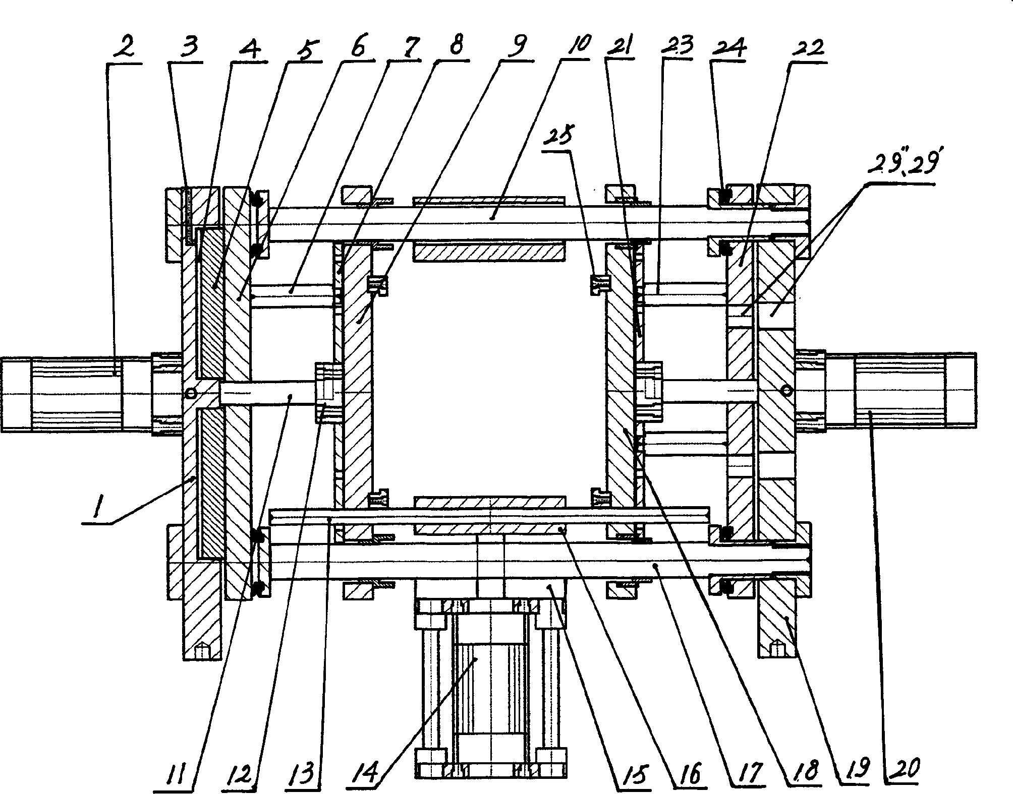
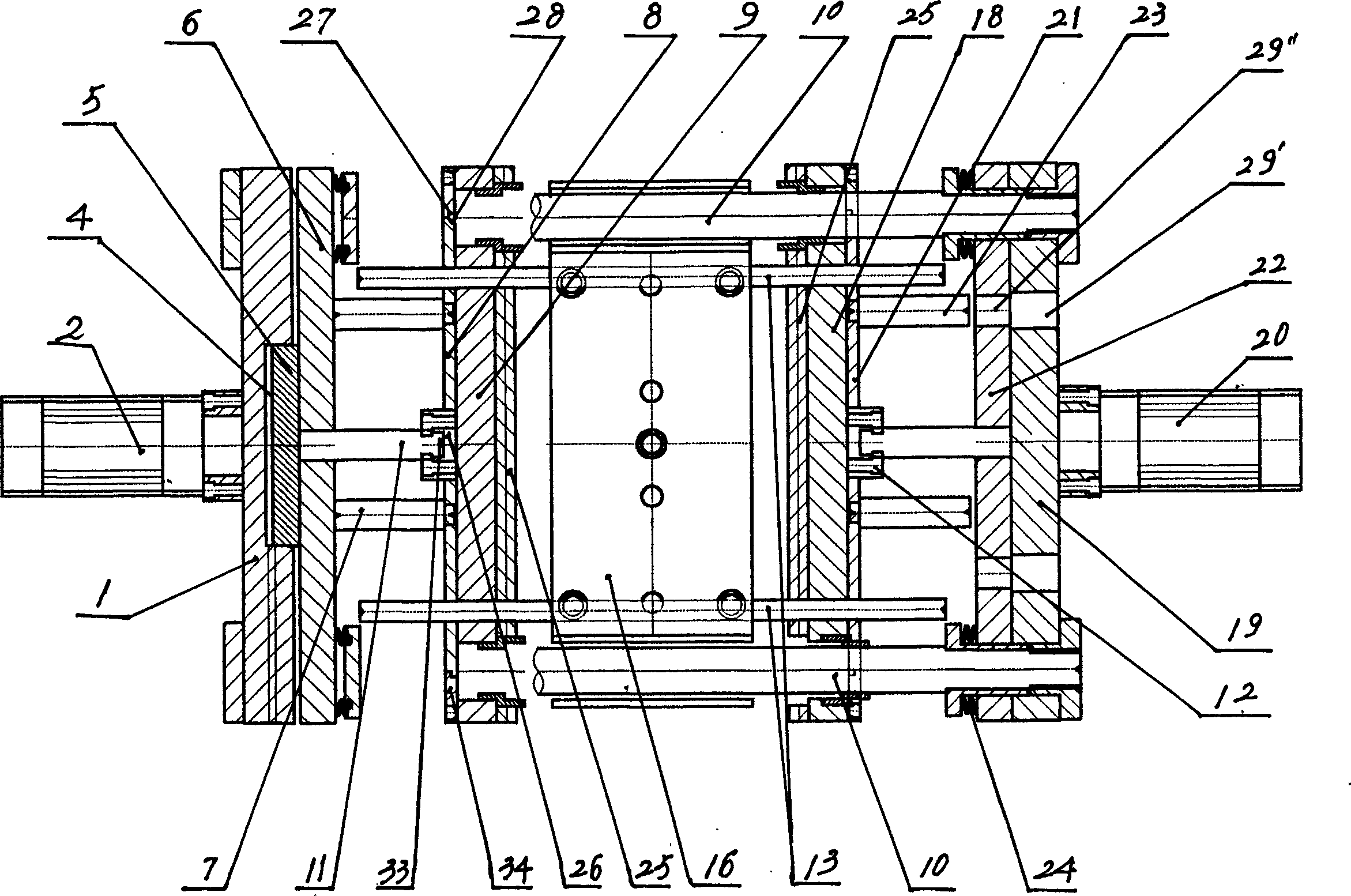
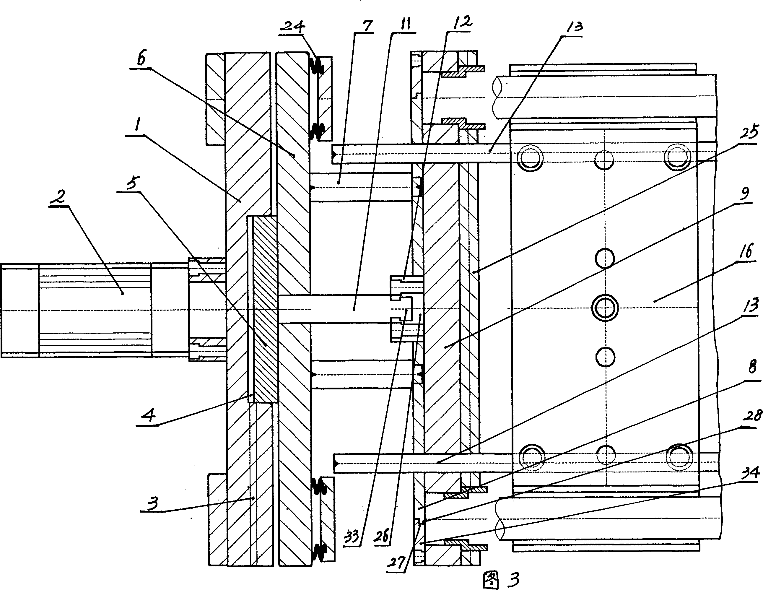
[0014] The invention discloses a mold clamping mechanism of a plastic bottle blowing machine, which comprises main components such as a fixed mold plate, a movable mold plate, and a mold opening and closing cylinder installed on a frame, and the fixed mold plate is connected and movable through an upper guide rod 10 and a lower guide rod 17 Formwork, the mold opening and closing cylinder is installed on the fixed formwork, and the piston rod of the cylinder is connected to the movable formwork. The main structural features are two fixed formworks, double cylinders and a bottom cylinder to drive the top mold column to close the mold, and there is a pressurized cylinder, that is, the above-mentioned The fixed templates are two symmetrical pieces, which are respectively A fixed template 1 and B fixed template 19. In particular, A opening and closing mold cylinder 2 and B opening and closing mold cylinder 20 are respectively installed on the two fixed templates, and A and B have two...


PUM


Abstract

The present invention relates to a mould-closing mechanism of plastic bottle-blowing machine. It comprises a fixed mould plate mounted on the machine frame, said fixed mould plate is connected with movable mould plate by means of upper and lower guide rods, on the fixed mould plate a cylinder for opening and closing mould is mounted, the piston rod of said cylinder is connected with movable mould plate. Its described fixed mould plate includes symmetrical two blocks of A and B, on said two blocks of fixed mould plates respectively are mounted mould-opening and closing cylinders of A and B, the piston rods of said two mould-opening and closing cylinders are respectively connected with movable mould plates of A and B. Besides, said invention also includes the components of upright column lifting fixing plate, top-moulding upright column, bottom mould cylinder, pressure piston and others.

Description

technical field [0001] The invention relates to a plastic blow molding machine, in particular to a mold clamping mechanism of the blow molding machine, which belongs to processing equipment for plastic containers. Background technique [0002] First, the plastic material is injected into a bottle tube by an injection molding machine, and then the bottle tube is stretched and blown into shape by a blow molding machine. For example, various mineral water bottles, oil bottles, etc. are usually processed by this method. The structure of the bottle blowing machine mainly consists of a frame and a mould, a mold clamping mechanism, a stretching and blowing mechanism, and an air delivery and control device. , because the bottle tube has a great mold expansion force in the process of blowing into a container, so the type and reliability of the mold clamping mechanism will directly affect the qualified rate of the product, production efficiency and the aestheti...

Claims


Application Information

Patent Timeline
Patent Type & Authority Applications(China)
IPC IPC(8): B29C49/56
Inventor 蔡桂森
Owner 蔡桂森
Why Eureka
Try Eureka