Cropping device

A cutting and cutting technology, applied in the field of cutting equipment, can solve the problems of large number of cylinders, occupation, and many parts, and achieve the effect of expanding the scope of use, reducing the use, and reducing costs

Pending Publication Date: 2020-07-03
WENZHOU KEWANG MACHINERY
View PDF0 Cites 6 Cited by
  • Summary
  • Abstract
  • Description
  • Claims
  • Application Information

AI Technical Summary

Problems solved by technology

[0004] In this type of structure, there are the following disadvantages: 1. The equipment is bulky: due to the large volume of the cylinder or hydraulic cylinder (used in cutting equipment), and the movement stroke of the cylinder itself, it needs to occupy a large working space , which also makes it difficult to reduce the size of the device
2. The number of driving cylinders is large: the cylinder is a single-point acting device, and it needs at least two to maintain balance when it is applied. Further accumulating and counting the cylinders used in the rubbing mechanism together, the number of cylinders will be no less than 4, resulting in production High cost and use cost
3. The structure is complex, there are many parts, and it is difficult to maintain: since the cutting mechanism and the flattening mechanism / heat insulation mechanism are on two different vertical planes, a transmission connection structure is required to make the two linked; moreover, the rubbing mechanism adopts an independent design , also has corresponding installation, transmission and other structures
In this category, there are the following disadvantages: 1. There are a large number of cylinders; 2. It is necessary to lay cylinder pipelines, which is inconvenient for installation and maintenance; 3. The response speed of the cylinder is slow. At 50 times / min), the cylinder obviously cannot keep up
[0006] It can be seen that the cutting equipment in the prior art has problems such as many parts, relatively scattered structure, poor integrity, low work efficiency, excessive equipment volume, and high cost.
Moreover, there is also the problem of slow response

Method used


Image

  • Cropping device
  • Cropping device
  • Cropping device

Examples


Embodiment 1

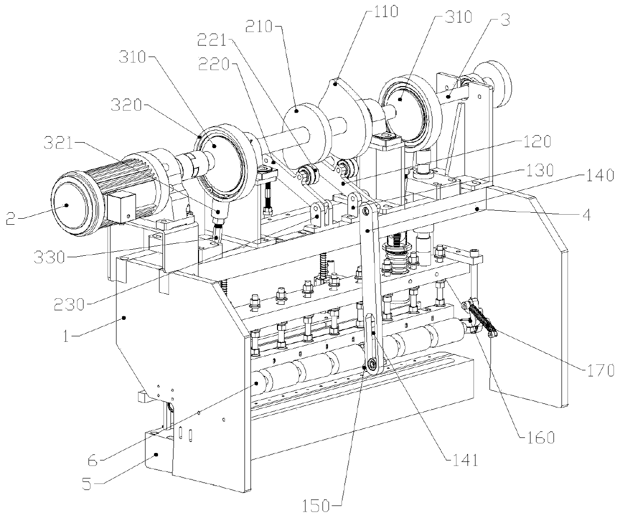
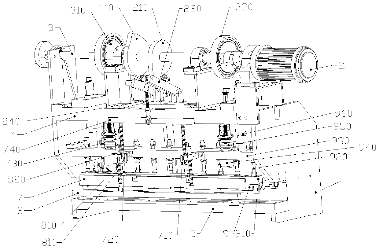
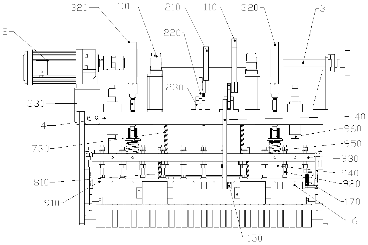
[0054] Example 1 combined figure 1 , figure 2 , image 3 As shown, a cutting device includes a cutting unit, and the linkage unit includes a bag rubbing unit, a bag pressing unit, and a cutting unit. The first transmission structure, the second transmission structure and the third transmission structure. In this embodiment, the cutting unit, bag rubbing unit, and bag pressing unit all use the combination of cam and transmission to realize specific actions. The cams and connecting rods in the cutting unit are respectively named as the first eccentric wheel 310 and the second Eccentric wheel 310, cam sleeve connecting rod 330, the cam and connecting rod in the rubbing bag unit are named as the first cam 110, the first connecting rod 140, and the cam and connecting rod in the bag pressing unit are named as the second cam 210, The second connecting rod 240 . Such as figure 1 As shown, the first eccentric wheel 310, the second eccentric wheel 310, the first cam 110, and the s...

Embodiment 2

[0085] Embodiment 2 In this embodiment, on the basis of Embodiment 1, an auxiliary flattening unit (also a kind of bag pressing unit) is added to cooperate with the cutting mechanism by adopting a mechanical structure. The auxiliary flattening unit includes an auxiliary rod 8 (that is, the auxiliary flattening member described in the summary of the invention), the two ends of the auxiliary rod 8 are fixedly connected with the second connecting rod 810, and the two ends of the connecting rod two 810 are respectively fixed to the fixing seat of the bag pressing unit through the second fixing seat 820 On -710, in this way, the auxiliary flattening unit, the bag pressing unit, and the cutter 9 unit can act synchronously, and before the cutter 9 performs cutting or synchronously with the cutter 9, the material is compressed for cutting.

[0086] The second fixed seat 820 is provided with a vertical through hole, the top of the connecting rod two 810 passes through the through hole f...

Embodiment 3

[0089] Embodiment 3 This embodiment provides a cutting device, which differs from Embodiments 1 and 2 in that a heat insulation unit is added to the linkage unit, and the heat insulation board 7 is a strip plate, which adopts heat insulation Made of material such as heat-insulating bakelite, the heat-shielding board 7 is usually arranged parallel to the cutter 9 . The heat insulation unit has its own independent fourth transmission structure and fourth cam. The fourth cam is also sleeved on the main shaft 3. The most protruding part of the fourth cam rotates to the bottom of the main shaft 3 no later than the first eccentric wheel 310. The second eccentric wheel 310.

[0090] In particular, the connection between the heat shield 7 and the fourth transmission structure can also be divided into two connection relationships: first, direct connection: the heat shield 7 is symmetrically arranged, and its center is connected to the fourth transmission structure of the fourth transmi...


PUM


Abstract

The invention belongs to the field of cropping equipment, and discloses a cropping device. At least two components of a cutter, a bag pressing piece, a bag twisting piece and a heat isolation piece are included. A rotary main shaft is arranged. A transmission structure for converting the rotation movement of the main shaft into the linear movement or for transmitting the rotation movement of the main shaft is arranged between the main shaft and at least two components. A rotary power source is adopted in the cropping device, a traditional air cylinder linear driving manner is replaced, the structure design can be optimized, the equipment size is reduced, and assembling and maintaining are convenient; and under the coaxial situation, the two ends of the cutter can act more easily, stress iskept consistent, and the cropping equipment has better action stability and can adapt to the occasion where the action speed is high.

Description

technical field [0001] The invention relates to the field of cutting equipment, in particular to a cutting device. Background technique [0002] Cutting equipment is a commonly used device for cutting plastic bags, cloth and other materials. Usually, a cold knife or a hot knife is used, and the opening of the cutting part of the hot knife is easy to stick. Its internal mechanism generally includes a mechanism for separating the upper and lower layers of the cut that is glued after cutting with a hot knife. , Cloth and other items to keep the flattening mechanism and heat insulation mechanism for heat insulation. [0003] In the prior art, one of the major categories is to link the flattening mechanism with the cutting mechanism installed by the hot knife: the flattening mechanism and the hot knife share more than one (including the original number) cylinders or hydraulic cylinders as driving elements, and the flattening mechanism Or the thermal insulation mechanism and the...

Claims


Application Information

Patent Timeline
Patent Type & Authority Applications(China)
IPC IPC(8): B26D1/08B26D7/02B26D7/08B26D7/26B26D5/16B26D7/27B31B70/14B31B70/02D06H7/00
CPCB26D1/085B26D5/16B26D7/025B26D7/08B26D7/2614B26D7/27B31B70/02B31B70/14D06H7/00
Inventor 郭矛黄步积
Owner WENZHOU KEWANG MACHINERY
Why Eureka
Try Eureka