Simulator for friction force between denture groove and correction string

A friction force, simulator technology, applied in the direction of arch wires, brackets, etc., can solve the problems of prolonging the clinical time of orthodontics, increasing the medical burden and pain of patients, and difficult to control teeth.

Inactive Publication Date: 2005-05-11
HARBIN INST OF TECH
View PDF0 Cites 5 Cited by
  • Summary
  • Abstract
  • Description
  • Claims
  • Application Information

AI Technical Summary

Problems solved by technology

Some are tight, some are loose, and some orthodontics are difficult to control the three directions of the teeth. Improper operation will cause the teeth to tilt, and there will be more rework, prol

Method used


Image

  • Simulator for friction force between denture groove and correction string
  • Simulator for friction force between denture groove and correction string
  • Simulator for friction force between denture groove and correction string

Examples


specific Embodiment approach 1

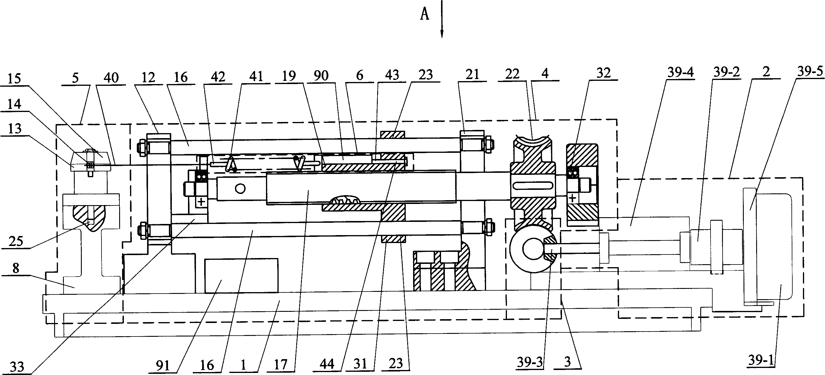
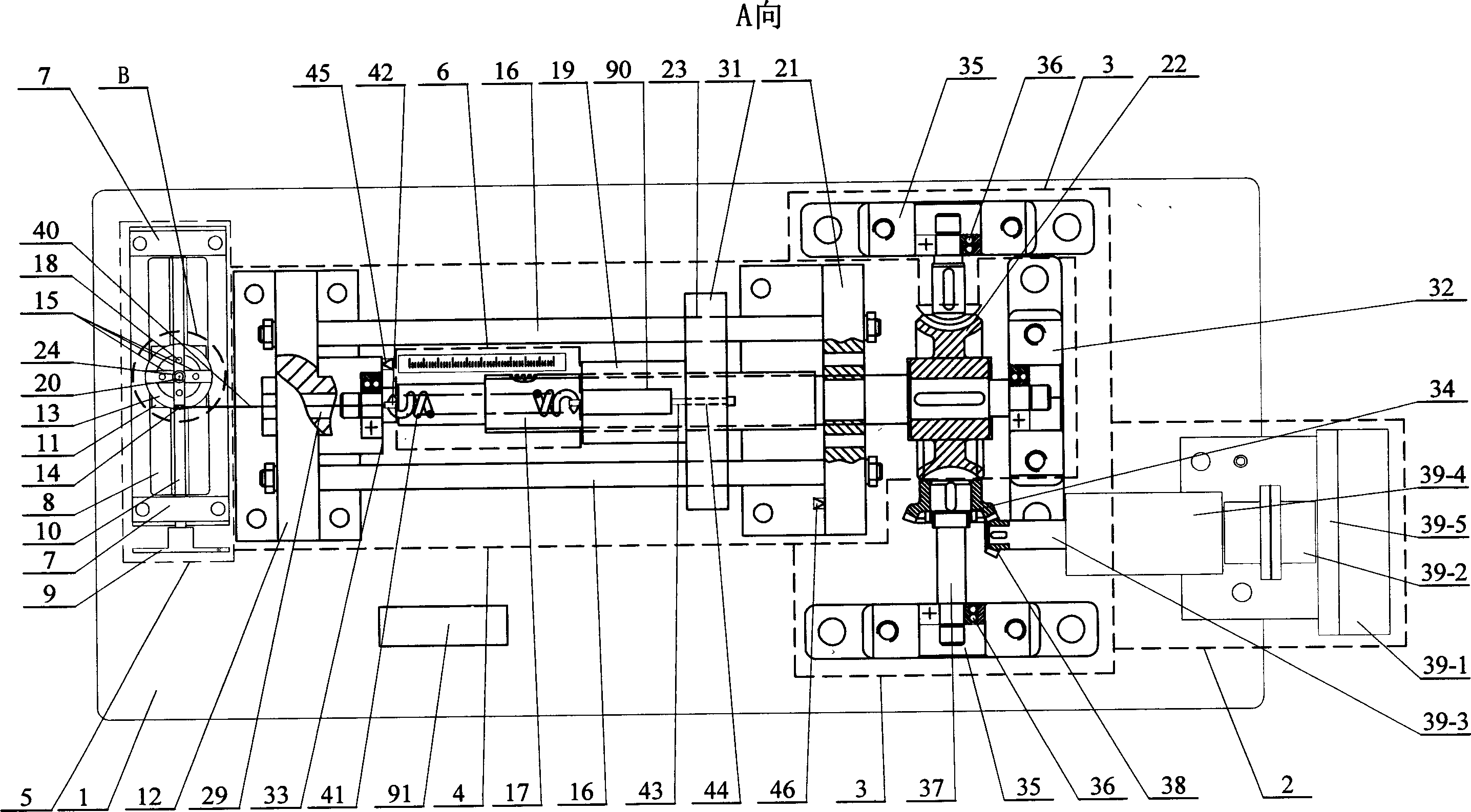
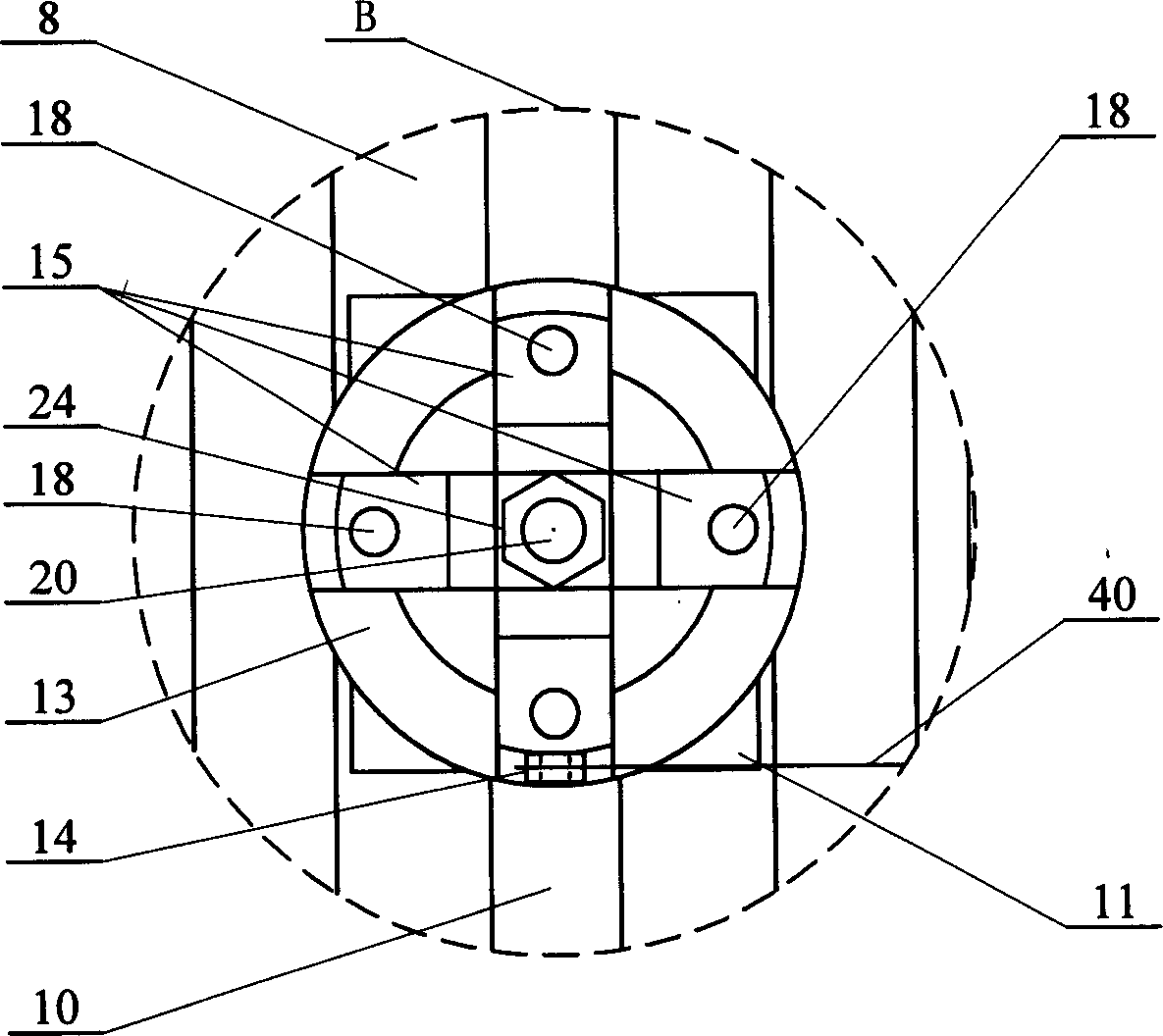
[0005] Specific implementation mode one: (see Figure 1-Figure 13 ) This embodiment consists of a base 1, a power unit 2, a speed change mechanism 3, a driving device 4, a bracket positioning device 5, a test device 6, a pull sensor 90, and a signal amplifier 91; the bracket positioning device 5 is fixed on the top of the base 1 The left end of the drive unit 4 is fixed on the upper part of the base 1 on the right side of the bracket positioning device 5, the speed change mechanism 3 is fixed on the base 1 on the right side of the drive unit 4, and the power unit 2 is fixed on the base 1 on the right side of the speed change mechanism 3 , the test device 6 is fixed on the upper side of the drive device 4, the power device 2 is connected to the transmission mechanism 3, the transmission mechanism 3 is connected to the drive device 4, and the pull sensor 90 is arranged on the right side of the test device 6 in the drive device 4 The signal amplifier 91 is fixed on the base 1, th...

specific Embodiment approach 2

[0006] Specific implementation mode two: (see figure 2 ) The difference between this embodiment and the specific embodiment one is that a left travel switch 45 and a right travel switch 46 are added on the driving device 4, and the left travel switch 45 is fixed on the right side of the lead screw left support 33, and the right The travel switch 46 is fixed on the left side of the right bracket 21, and other components and connections are the same as those in the first embodiment. The increased left travel switch 45 and right travel switch 46 can ensure the safe operation of the driving device.

[0007] Working principle: The working process of the present invention is carried out according to the three-dimensional movement characteristics of the orthodontic teeth of the clinical patient and the orthodontic needs (first determine whether the tooth to be treated is the tooth on the left and right of the upper jaw or the tooth on the left and right of the lower jaw) and corresp...


PUM


Abstract

A simulator for the friction between the tooth deformity correcting bow wire and the supporting slot in order to test the friction force is composed of a base, a driver, a speed variator fixed on the base on the right of driver, a tester fixed in said driver, a tension sensor in the driver on the right of tester, and a signal amplifier with input connected to the output of tension sensor.

Description

Technical field: [0001] The invention relates to a testing device for simulating the frictional force between an arch wire and a bracket groove in the process of orthodontic treatment of oral cavity teeth. Background technique: [0002] At present, in the orthodontics departments at home and abroad, when performing orthodontics, the arch wire is fastened in the groove of the bracket by ligature wire. To create traction, act on the orthodontic tooth, causing the tooth to move. In foreign oral orthodontic methods, self-locking brackets are also used for fastening to complete arch wire fastening for orthodontics. However, in all the actual clinical ligation and fastening processes, it is difficult to accurately control the magnitude and direction of the torque force acting on each tooth, and it is also different due to the arrangement of each person's teeth, the twist angle of the arch wire, and the degree of orthodontics. There are different. Even if it is fastened with sel...

Claims


Application Information

Patent Timeline
IPC IPC(8): A61C7/12A61C7/28
Inventor 徐实谦徐永涛
Owner HARBIN INST OF TECH
Why Eureka
Try Eureka