Fluid driving bending joint of spiral spring frame

A technology of helical springs and bending joints, applied in the direction of claw arms, manipulators, manufacturing tools, etc., can solve the problems of energy consumption, high manufacturing cost, and complex structure, and achieve high dynamic control accuracy, easy axial deformation, and small fluid flow Effect

Inactive Publication Date: 2005-05-11
JIANGNAN UNIV
View PDF1 Cites 14 Cited by
  • Summary
  • Abstract
  • Description
  • Claims
  • Application Information

AI Technical Summary

Problems solved by technology

[0002] Before the present invention was made, in the prior art, for bending joints: generally, various types of motors or hydraulic pressure were used as power, and combinations of various mechanical structures, hydraulic cylinders, motors, etc. were used as actuators; the above methods were Rigid structure, high precision control requirements, complex structure, large volume, high manufacturing cost
There is also a rubber wall driven by air pressure (a circular rubber tube that is deformable and stores energy, and a helical wire that restricts radial expansion is clamped inside the tube

Method used


Image

  • Fluid driving bending joint of spiral spring frame
  • Fluid driving bending joint of spiral spring frame
  • Fluid driving bending joint of spiral spring frame

Examples


Embodiment Construction

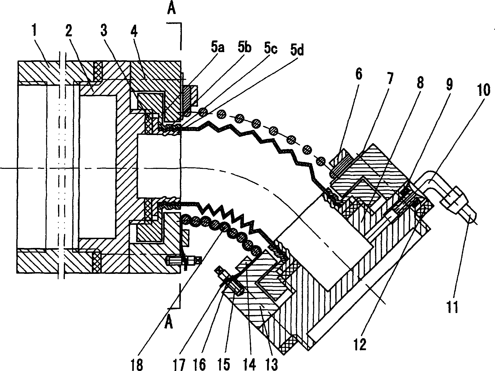
[0028] Below the present invention will be further described in conjunction with the implementation of scheme I in the accompanying drawings:

[0029] The joint of plan I is mainly composed of intermediate section 1, head seat 2, large sealing ring 3, spring fixing seat 4, connecting sealing nut 5a, fastening shell 5b, elastic wave shell 5c, flange inner sleeve 5d, spring fixing pressure plate 6, Adjusting gasket 7, tailstock 8, small sealing ring 9, right-angle pipe joint 10, hose 11, thickness adjusting ring 12, tensioning wire seat 13, wire guide frame 14, tensioning screw 15, fixing screw 16, fixing wire 17, helical spring 18, annular weft 19, winding warp 20 etc. constitute.

[0030] Its specific implementation method is:

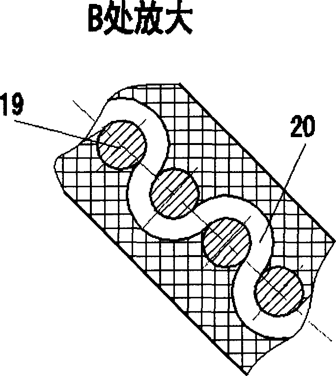
[0031] (1) The longitudinal section shape of the single elastic wave shell of the elastic wave shell 5c is "V", "U" or "Ω". through

[0032] 20. In this way, the elastic wave shell 5b is not easily deformed in the radial direction, and its bearing c...


PUM


Abstract

A flexible joint with spiral spring as its skeleton and driven by fluid for robot features that the axial extension at one side of spiral spring is restricted by a fixing wire and its another side can be axially extended, so realizing bending. When there is no external force, the bent angle of joint is relative to the air pressure in joint. When it is working, its action force is increased with the air pressure in it.

Description

Technical field: [0001] The invention relates to a helical spring framework fluid-driven bending joint, which can be used as elbows, legs and other joints of robots, and is also suitable for mechanical fingers composed of multiple bending joints, and multiple mechanical fingers can be combined The utility model relates to an operating manipulator, as an executive mechanism of automation equipment, and belongs to the technical field of robot and manipulator application. Background technique: [0002] Before the present invention was made, in the prior art, for bending joints: generally, various types of motors or hydraulic pressure were used as power, and combinations of various mechanical structures, hydraulic cylinders, motors, etc. were used as actuators; the above methods were The rigid structure requires high control precision, and the structure is complicated, the volume is large, and the manufacturing cost is high. There is also a rubber wall driven by air pressure (a...

Claims


Application Information

Patent Timeline
IPC IPC(8): B25J18/00B25J18/02
Inventor 章军须文波吕兵
Owner JIANGNAN UNIV
Why Eureka
Try Eureka