Cooling plate for a metallurgical furnace and method for manufacturing such a cooling plate

A cooling plate and metallurgical furnace technology, applied in furnace cooling devices, furnace cooling, cooling devices, etc., can solve the problems of expensive copper cooling plates, difficult to remove the casting sand of cooling pipes, and the cooling pipes are not strong enough to improve the use of Longevity, reduced maintenance costs, good wear resistance

Inactive Publication Date: 2005-05-11
PAUL WURTH SA
View PDF5 Cites 12 Cited by
  • Summary
  • Abstract
  • Description
  • Claims
  • Application Information

AI Technical Summary

Problems solved by technology

Disadvantages of this method are: it is difficult to remove the casting sand from the cooling pipes, and / or the cooling pipes of cast iron are often poorly formed and the cooling pipes are often not strong enough
Therefore, copper cooling plates cannot be used for cooling plates in furnace areas exposed to dangerous mechanical stress
Also, copper cooling plates are much more expensive than cast iron cooling plates

Method used


Image

  • Cooling plate for a metallurgical furnace and method for manufacturing such a cooling plate
  • Cooling plate for a metallurgical furnace and method for manufacturing such a cooling plate

Examples


example

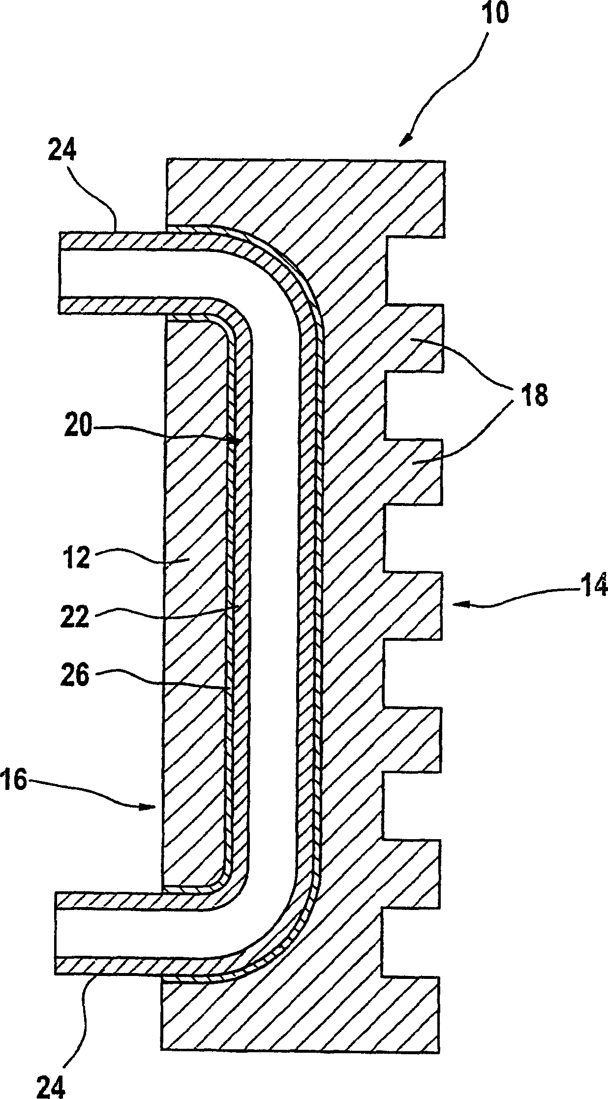
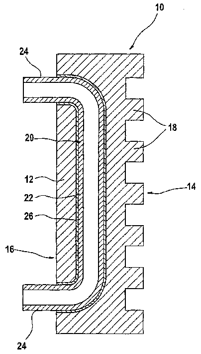
[0041] Cooling plate samples were fabricated as described above. A cooling tube with an outer diameter of 75 mm and a wall thickness of 10 mm was used. Steel cooling tubes are provided with a 7mm thick copper layer. A steel cooling pipe with a 7 mm thick copper layer was placed in a mold and cast iron at a temperature of 1250° C. was cast in the mold. After curing a 200mm thick cooling plate was obtained, which meant that the copper sleeve was covered by about 55mm of cast iron.

[0042] Cutting the cooling plate transversely can effectively observe the internal structure of the vertical cold wall. After cutting, it can be observed that the thick and uniform copper jacket is around the cooling tube without any air gap between the cast iron body and the copper jacket. At the junction of the tube / sleeve, due to the shrinkage of the copper, it is always in a tight connection. Therefore, the two junctions of the copper sleeve are in close contact, and the steel cooling pipe ca...


PUM

PropertyMeasurementUnit
thicknessaaaaaaaaaa
thicknessaaaaaaaaaa
thicknessaaaaaaaaaa

Abstract

The invention discloses a cooling plate (10) for a metallurgical furnace, which comprises a cast iron cooling plate body (12) made of ferrous metal and at least one steel cooling pipe ( 20). The thickness of the metal sleeve (26) on the outer surface of the steel cooling pipe (20) in the cooling plate body (12) is in the range of millimeters, and the metal sleeve (26) is made of copper, copper alloy, nickel and nickel alloy. Made of metal of choice.

Description

technical field [0001] The present invention generally relates to a cooling plate for a metallurgical furnace and a method of manufacturing the cooling plate. Background technique [0002] Cooling plates, also called "staves" have been used in blast furnaces for hundreds of years. These cooling plates are positioned inside the furnace armor and have internal coolant ducts connected to the cooling system of the furnace. The surface of the cooling plate facing the furnace interior may be lined with refractory material. [0003] Such cooling plates can be produced in a number of different ways. [0004] In the first method, the mold used to cast the cooling plate body is provided with one or more sand cores for forming the internal coolant channels. The liquid cast iron is then poured into the mold. Disadvantages of this method are that it is difficult to remove the casting sand from the cooling pipes, and / or the cast iron cooling pipes are often poorly formed and the cooli...

Claims


Application Information

Patent Timeline
Patent Type & Authority Applications(China)
IPC IPC(8): B22D19/00C21B7/10F27B1/24F27D1/12F27D9/00
CPCC21B7/10F27B1/24F27D1/12F27D2009/0048F27D2009/0051F27D2009/0062
Inventor 吉里·兹拉马尔盖伊·西伦乔治斯·拉塞尔
Owner PAUL WURTH SA
Why Eureka
Try Eureka