
Liquid crystal display device

A technology of liquid crystal display device and liquid crystal layer, applied in the direction of transistor, static indicator, optics, etc., can solve the problem of inability to obtain black display, and achieve the effect of excellent transmission characteristics and good display

Inactive Publication Date: 2005-05-18
SANYO ELECTRIC CO LTD
View PDF1 Cites 8 Cited by
  • Summary
  • Abstract
  • Description
  • Claims
  • Application Information

AI Technical Summary

Problems solved by technology

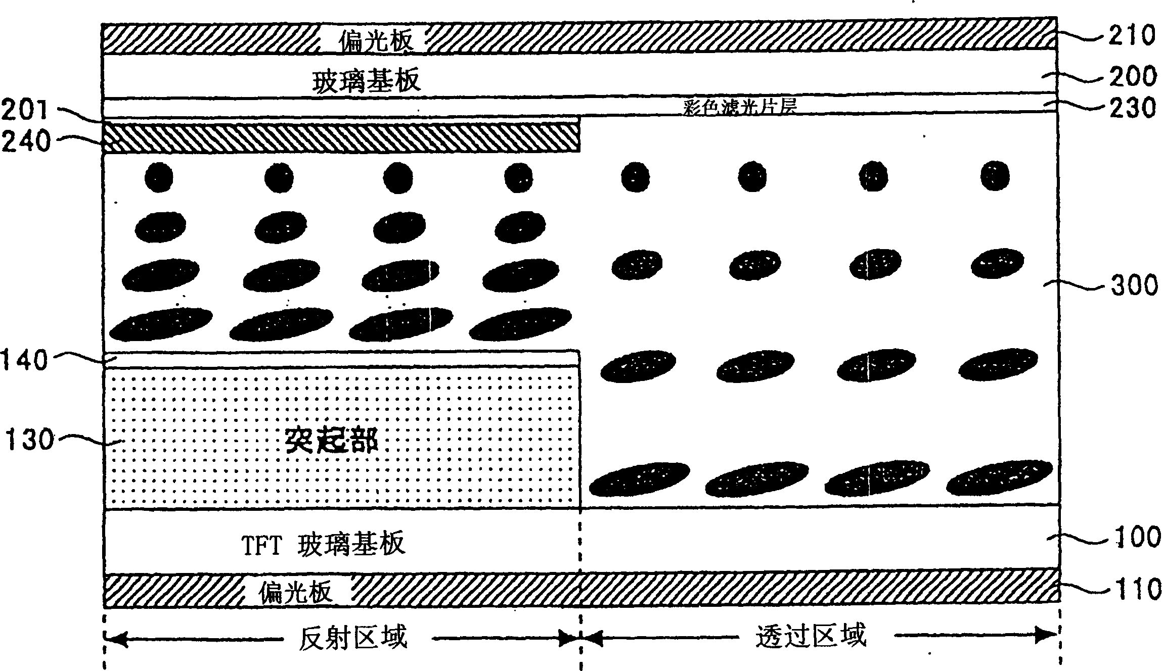
[0009] However, when there is no first phase difference plate 220, a voltage is applied to the liquid crystal layer 300, and when the long axes of the liquid crystal molecules in the liquid crystal layer 300 stand upright, the liquid crystal molecules pass through the polarizer 210, the color filter side glass substrate 200, and the liquid crystal layer 300. , the reflected light reflected by the reflective electrode 140 is directly emitted to the outside in the opposite path again in the state of no phase difference, so black display cannot be obtained

Method used


Image

  • Liquid crystal display device
  • Liquid crystal display device
  • Liquid crystal display device

Examples


Embodiment Construction

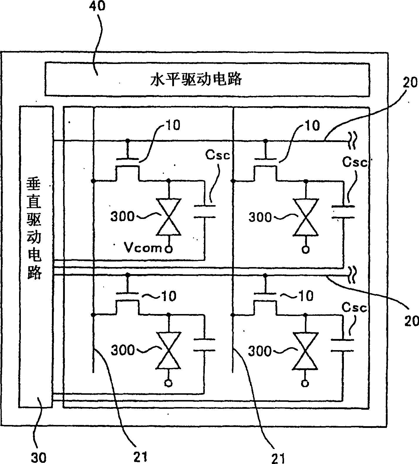
[0047] Next, embodiments of the present invention will be described with reference to the drawings. First, the liquid crystal display device of the first embodiment will be described. figure 1 is an overall configuration diagram of the liquid crystal display device, figure 2 It is a cross-sectional view of the configuration of one pixel. also, figure 2 in, with Figure 9 The same components are assigned the same symbols, and descriptions thereof are omitted.

[0048] The liquid crystal display device such as figure 1 As shown, a plurality of pixels arranged in a matrix of n columns and m rows are provided, and each pixel has a pixel selection TFT 10, a liquid crystal layer 300, and a storage capacitor Csc. The gate of the pixel selection TFT 10 is connected to the gate line 20 extending in the row direction, and the drain is connected to the data line 21 extending in the column direction. The gate line 20 of each row is sequentially supplied with a gate scan signal fr...


PUM

PropertyMeasurementUnit
refractive indexaaaaaaaaaa

Abstract

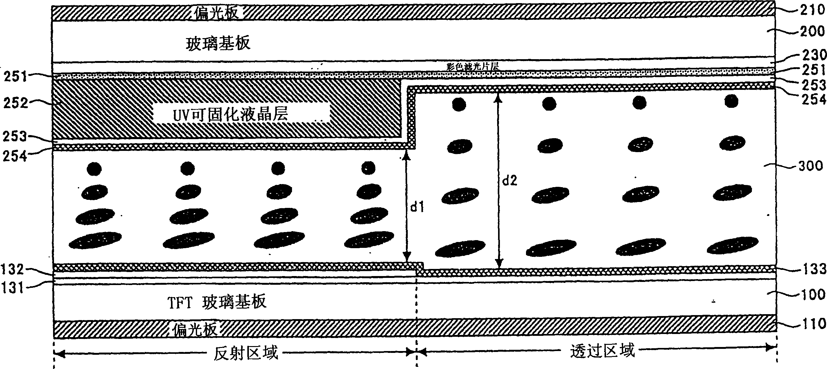
Provided is a liquid crystal display device of which the display property of semiconductor LCD can be improved, and thinning down of thickness and cost lowering of LCD can be achieved. In a reflection area, the side of color filter opposite the liquid crystal layer (300) of glass substrate (200) is coated with an UV curable liquid crystal (240) and then subjected to an UV irradiation for curing. Since the UV curable liquid crystal (240) performs as a differential phase shifter, unlike the prior art, laminating the differential phase shifter onto the glass substrate or TFT glass substrate on the color filter side is not needed. In addition, because the UV curable liquid crystal (240) is easy to be patterned, the pattern formation can be selectively made only on the reflection area.

Description

technical field [0001] The present invention relates to a liquid crystal display device, in particular to a transflective liquid crystal display device in which both a reflective area and a transmissive area are provided in each pixel. Background technique [0002] Liquid crystal display devices (hereinafter referred to as LCDs) are characterized by thinness and low power consumption, and are currently widely used in monitors of computers and monitors of mobile information devices such as mobile phones. LCDs include transmissive LCDs and reflective LCDs. The transmissive LCD uses a transparent electrode as the pixel electrode for applying voltage to the liquid crystal, and arranges a backlight light source behind the LCD panel, and controls the amount of light transmitted by the backlight through the LCD panel. Bright display is possible. However, since the backlight is always turned on for display, the power consumption is large, and in an environment with strong external...

Claims


Application Information

Patent Timeline
Patent Type & Authority Applications(China)
IPC IPC(8): G02B5/30G02F1/133G02F1/1335G02F1/13363G02F1/1337G02F1/136H01L29/786
CPCG02F1/133528G02F1/13363
Inventor 小间德夫三井雅志
Owner SANYO ELECTRIC CO LTD
Learn More