

Burner of biomass gasification gas fuel kitchen range
A technology for gas stoves and biomass, which is applied to gaseous heating fuels, heating fuels, household appliances, etc., can solve the problems of large height and size of stoves, inconvenient moving of stoves, and large workload of stoves, and achieves reduction in height and size, Easy and fast installation
- Summary
- Abstract
- Description
- Claims
- Application Information
AI Technical Summary
Problems solved by technology
Method used
Image

Examples
Embodiment Construction
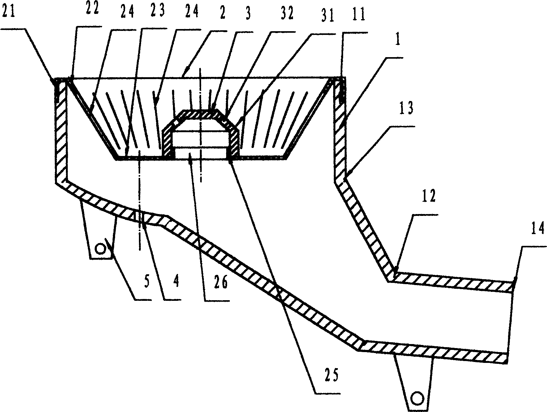
[0007] from figure 1 It can be seen that the burner head of the biomass gasification gas cooker of the present invention has a burner body 1, a diverter bowl 2, and a diverter cap 3. The burner body 1 includes a head 11 and a handle 12, and the height of the head 11 is slightly greater than The height of the diverter bowl 2, the handle 12 is inclined, that is, the central axis of the handle and the axis of the head form a certain angle. journey. The end 13 of the handle 12 connected to the head is higher than the intake end 14 of the handle, so that the water can flow back to the blowdown valve of the system for discharge, and there is no need to install a blowdown valve on the burner body, thereby further reducing the burner pressure. The height of the body finally reduces the overall height of the present invention to the same height as that of the existing liquefied gas range burner. The diverter bowl 2 is seated in the head 11 of the burner body 1 with its bowl edge 21. ...
PUM
 Abstract
Description
Claims
Application Information