
Remodeled integral stand and injection cylinder of injection moulding machine

A technology for injection cylinders and injection molding machines, which is applied in the field of injection molding machines, and can solve problems such as increased temperature accumulation of injection oil, increased power consumption, and easy damage to the hydraulic valve of the sealing ring of the injection cylinder.

Inactive Publication Date: 2005-06-01
蔡桂森
View PDF0 Cites 0 Cited by
  • Summary
  • Abstract
  • Description
  • Claims
  • Application Information

AI Technical Summary

Problems solved by technology

In the prior art, the integral seat and the injection cylinder are integrally connected, because the barrel continuously heats the plastic material during work, so part of the heat of the barrel is transferred to the integral seat, and the integral seat directly affects the injection cylinder after being heated. The heat is brought into the oil tank through the oil medium, so that the temperature of the injected oil is continuously accumulated and increased, and finally the sealing ring and hydraulic valve of the injected oil cylinder are easily damaged due to the influence of high temperature, especially in summer
And because the injection cylinder is integrally connected with the integral seat, it is very troublesome to process and install, disassemble and repair the parts in the cylinder. It takes a long time to replace the sealing ring each time, which directly affects the normal production time and low work efficiency.
On the other hand, because the injection cylinder keeps taking away heat, the temperature of the barrel close to the overall seat does not rise, which directly affects the heating of the plastic material by the barrel, resulting in increased power consumption.
When the barrel outlet of the injection molding machine is injected, there will still be hot plastic flowing out, which is called salivating plastic. During the pre-molding process, there is negative pressure in the barrel. The existing technology produces negative pressure after injection molding, and the speed of preventing salivation is slow.

Method used


Image

  • Remodeled integral stand and injection cylinder of injection moulding machine
  • Remodeled integral stand and injection cylinder of injection moulding machine
  • Remodeled integral stand and injection cylinder of injection moulding machine

Examples


Embodiment Construction

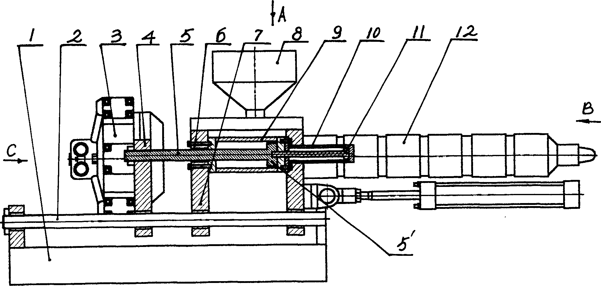
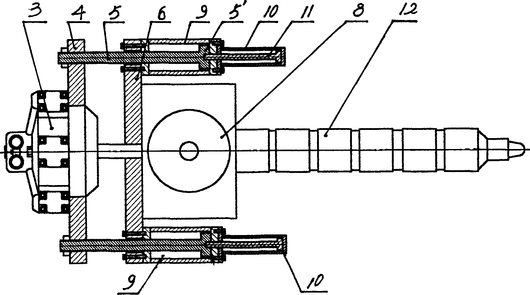
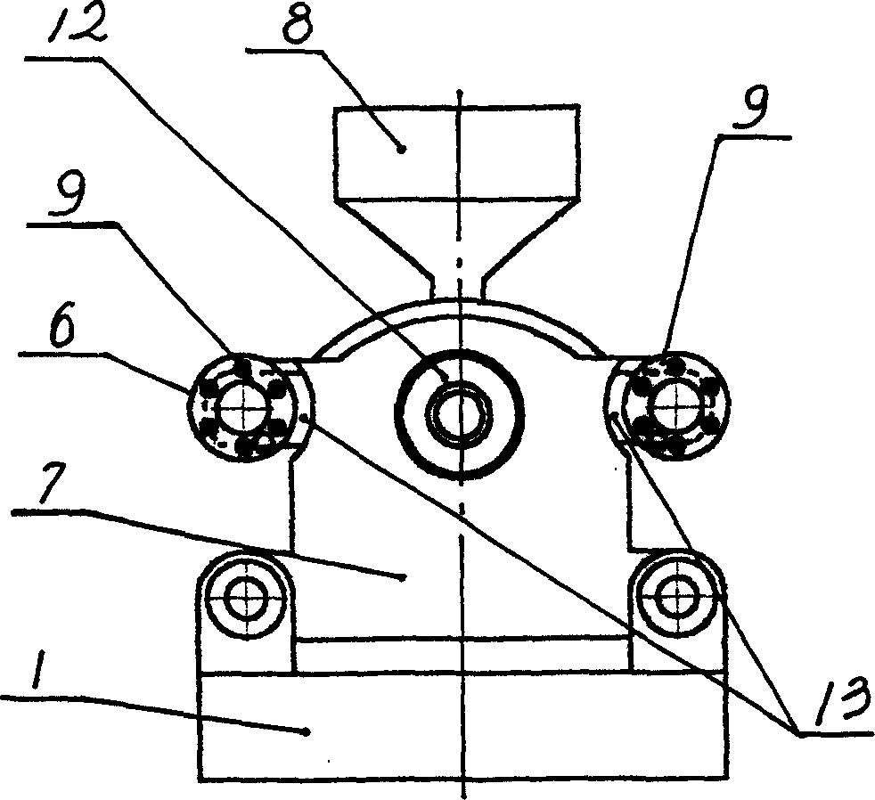
[0009] The invention discloses an improved design of the integral seat and the injection oil cylinder of the injection molding machine, involving an oil motor 3 and an integral seat 7 installed on the injection molding machine frame 1 (or through the guide rod 2), and the integral seat 7 has a hopper 8. The integral seat is connected to the barrel 12, and the oil motor is made with bracket ears 4. The main improvement design is that the two sides of the integral seat 7 are equipped with connecting ears 6, such as image 3 As shown, the injection cylinder 9 is installed in the connecting ear 6, such as figure 2 As shown, since the bracket ears 4 have been formed on the oil motor 3, such as figure 2 , Figure 4 Shown, support ear 4 is shaped on piston hole, makes the piston rod 5 of injection cylinder 9 penetrate in the piston hole of oil motor support ear 4. In this way, the heat of the barrel 12 (plastic heating runner) is not transmitted to the injection cylinder after be...


PUM


Abstract

The improved integral seat and injection oil cylinder for injection molding machine includes integral seat, oil motor with support ears and installed onto the seat, material bin on the seat and material barrel connected to the seat. The improvement includes the seat with connecting ears on two sides, injection oil cylinder installed onto the connecting ears, and the piston rod of the injection oil cylinder penetrating the hole in the support of oil motor. The improved structure overcomes the effect of the heat from the material barrel on the injection oil cylinder to avoid the damage of the sealing ring in the injection oil cylinder, hydraulic valve, etc., reducing the heat loss of the material barrel to save energy and facilitates the manufacture, installation and maintenance of the injection oil cylinder,

Description

technical field [0001] The invention relates to an injection molding machine, in particular to an integral seat and an injection cylinder of the injection molding machine. Background technique [0002] One end of the base of the injection molding machine is equipped with a mold and a mold clamping assembly, while the other end is equipped with an injection molding assembly and an oil motor. The main parts of the injection molding assembly are the integral seat, the barrel connected to the integral seat, and the injection cylinder. In the prior art, the integral seat and the injection cylinder are integrally connected, because the barrel continuously heats the plastic material during work, so part of the heat of the barrel is transferred to the integral seat, and the integral seat directly affects the injection cylinder after being heated. The heat is brought into the oil tank through the oil medium, so that the temperature of the injected oil is continuo...

Claims


Application Information

Patent Timeline
IPC IPC(8): B29C45/03
Inventor 蔡桂森
Owner 蔡桂森
Learn More