
Infra-red light ratio pulsation detecting apparatus and detecting method for shape of flocculation in water

A detection device, infrared light technology, applied in the measurement device, transmittance measurement, scattering characteristic measurement and other directions, can solve the problems of difficult modeling, low reliability, large investment and so on

Inactive Publication Date: 2005-06-01
HARBIN INST OF TECH
View PDF0 Cites 6 Cited by
  • Summary
  • Abstract
  • Description
  • Claims
  • Application Information

AI Technical Summary

Problems solved by technology

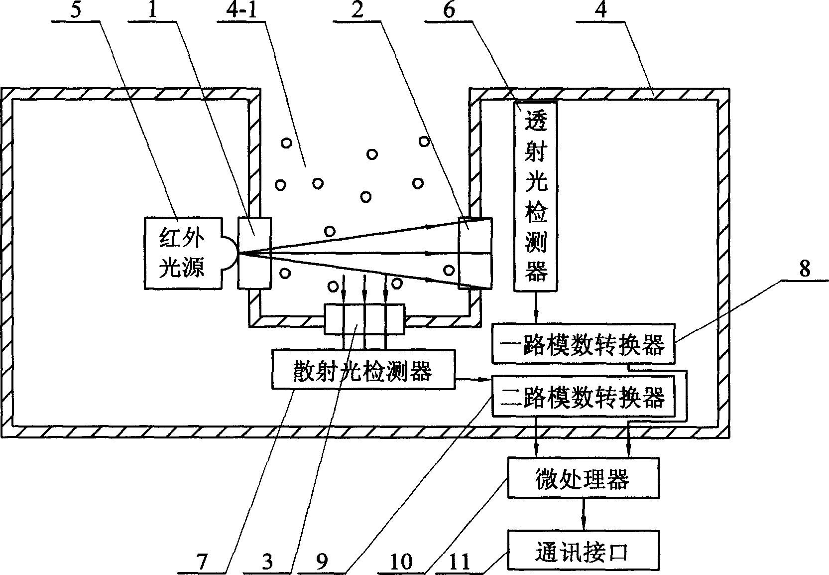
[0003] The purpose of the present invention is to provide a flocculation dosing process for water treatment in order to overcome the disadvantages of large investment, low reliability, difficult modeling, poor precision, and difficult operation and maintenance in the traditional detection method and device for floc morphology in water. Infrared light ratio pulsation detection device and detection method for floc form in water

Method used


Image

  • Infra-red light ratio pulsation detecting apparatus and detecting method for shape of flocculation in water
  • Infra-red light ratio pulsation detecting apparatus and detecting method for shape of flocculation in water

Examples


specific Embodiment approach 1

[0007] Specific implementation mode one: the following combination figure 1 This embodiment will be specifically described. The device of the present invention consists of an infrared light source 5, a scattered light detector 7, a transmitted light detector 6, an analog-to-digital converter 8, an analog-to-digital converter 9, a microprocessor 10, a communication interface 11, and a transparent window 1 , No. 2 transparent window 2, No. 3 transparent window 3 and sensor housing 4. Infrared light source 5, scattered light detector 7, transmitted light detector 6, one-way analog-to-digital converter 8, and two-way analog-to-digital converter 9 are set In the sensor housing 4, No. 1 transparent window 1, No. 2 transparent window 2, and No. 3 transparent window 3 are inlaid on the sensor housing 4 and seal the sensor housing 4, and the transmitted light detector 6 is installed in the No. 2 transparent window. 2 inside and opposite to the infrared light source 5 installed on the ...

specific Embodiment approach 2

[0008] Specific embodiment two: the detection method of infrared light ratio pulsation of floc form in water, it is realized through the following steps: one, through the infrared light source 5, make the infrared laser line pass through the water sample to be detected after adding the flocculant and stirring; two 1. Use the transmitted light detector 6 to receive the infrared laser rays that pass through the water sample to be detected, and simultaneously use the scattered light detector 7 to receive the scattered light generated after the infrared laser rays irradiate the water sample to be detected in a direction perpendicular to the infrared laser rays; , the transmitted light detector 6 converts the received light signal into a transmitted photoelectric signal proportional to the light intensity, and the scattered light detector 7 converts the received light signal into a scattered photoelectric signal proportional to the light intensity; four, The transmitted photoelectri...


PUM


Abstract

The present invention is one infrared proportional pulsation detecting device and method for flock state in water and belongs to the field of optical detection technology for flock state in water treatment. The infrared proportional pulsation detecting device includes transmitted light detector inside the No. 2 window, infrared source inside the No. 1 window opposite to the transmitted light detector, and scattered light detector inside the No. 3 window perpendicular to the infrared source. The electric signals the transmitted light detector and the scattered light detector output are converted into digital signal in the A / D converter, and the digital signal is processed in the microprocessor to obtain the flock state number signal output via the communication interface. The present invention has less investment and high effect, and is especially suitable for use in controlling the throwing of flocculant in water treatment.

Description

Technical field: [0001] The invention belongs to a floc morphology optical detection device and method applied to the flocculation dosing process of water treatment. Background technique: [0002] Flocculation is the most important treatment process in the water purification system, and it is also the main component of the cost of water production. The accuracy of flocculant dosage directly affects the whole process of water treatment. The traditional flocculation dosing detection and control technology mainly includes: the mathematical model that needs to detect various apparent parameters that affect the flocculation effect (flow rate, turbidity, pH value, alkalinity, temperature of raw water, flow rate, concentration, efficiency, etc. of coagulant) method, a simplified method that only detects some parameters, a semi-automatic method that detects one or two parameters above, a model filter method or a model inclined tube method, etc. They all have insurmountable shortcom...

Claims


Application Information

Patent Timeline
IPC IPC(8): G01N21/17G01N21/49G01N21/59
Inventor 南军
Owner HARBIN INST OF TECH
Learn More