Non-linear evolutional correction method for levelmeter of linear frequency-modulation radar

A radar level meter and linear frequency modulation technology, which is applied to the liquid level indicator for physical variable measurement, radio wave measurement system, liquid/fluid solid measurement, etc. , to achieve the effect of improving production efficiency, simple production and debugging, and high linearity

Inactive Publication Date: 2005-06-29
TAIYUAN UNIV OF TECH
View PDF0 Cites 18 Cited by
  • Summary
  • Abstract
  • Description
  • Claims
  • Application Information

AI Technical Summary

Problems solved by technology

[0004] The purpose of the nonlinear evolution correction method of the linear frequency modulation radar level meter of the present invention is to provide a simple correction method of frequency modulation linearity without adding any hardware, to solve the current d...

Method used


Image

  • Non-linear evolutional correction method for levelmeter of linear frequency-modulation radar
  • Non-linear evolutional correction method for levelmeter of linear frequency-modulation radar
  • Non-linear evolutional correction method for levelmeter of linear frequency-modulation radar

Examples


Embodiment approach 1

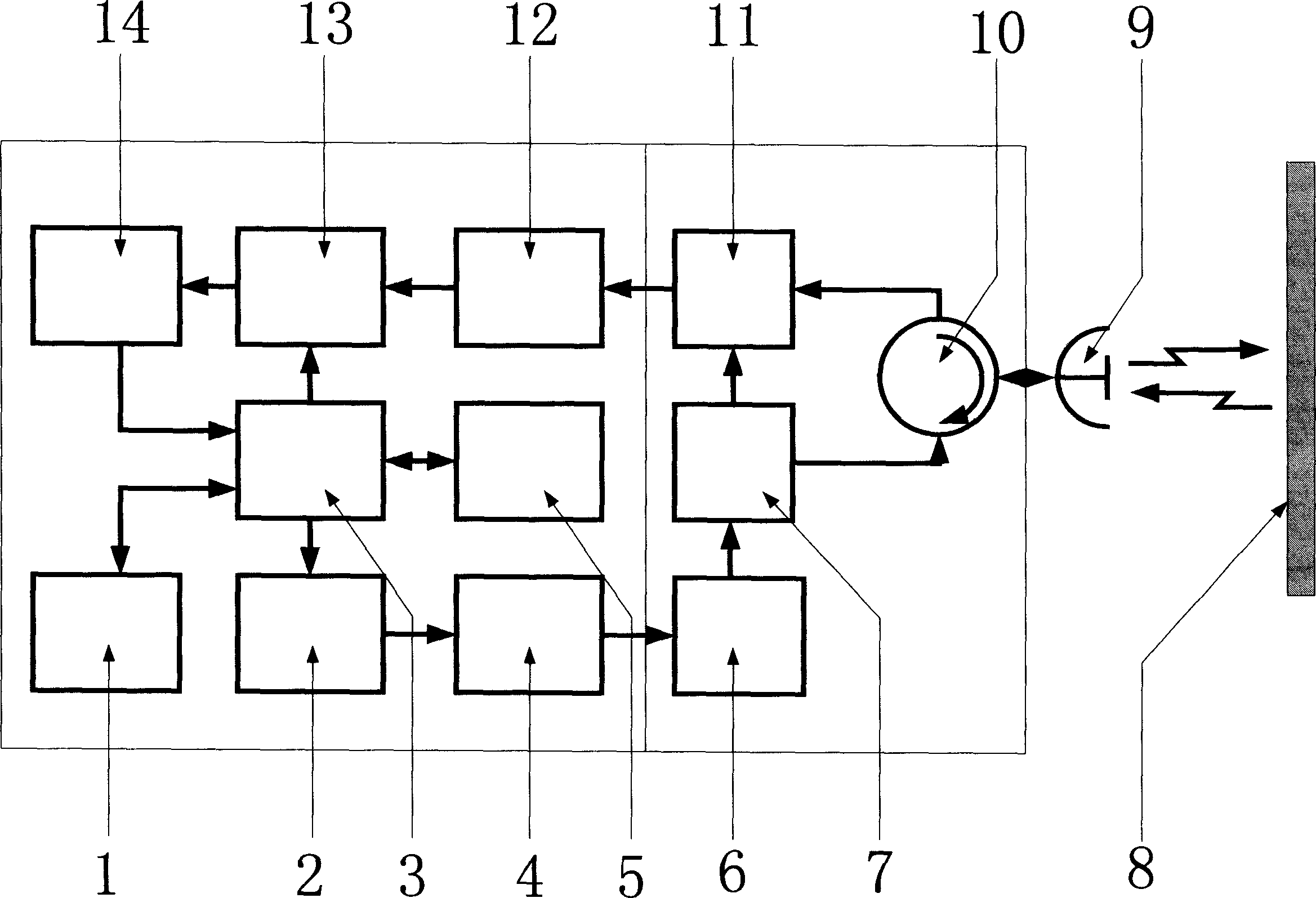
[0052] Implementation mode 1 such as figure 1 As shown, when calibrating, a metal plate is placed in front of the radar level gauge perpendicular to the axial position of the antenna. The distance between the radar level gauge and the metal plate can be measured and input into the relevant parameters of the radar level gauge as For reference, to speed up the calibration process, the digital signal processor 3 outputs a digital signal to the D / A converter 2, which is converted into a voltage signal, which forms the control voltage of the voltage-controlled oscillator 6 of the microwave unit through the buffer amplifier 4 to stimulate the voltage-controlled oscillation The microwave FM signal is generated by the microwave FM signal, and the microwave FM signal is transmitted by the antenna 9 through the circulator 10 after the coupler 7, and the signal coupled by the coupler 7 is sent to the mixer 11 as a reference signal, and the target object 8 reflects the echo through the circu...

Embodiment approach 2

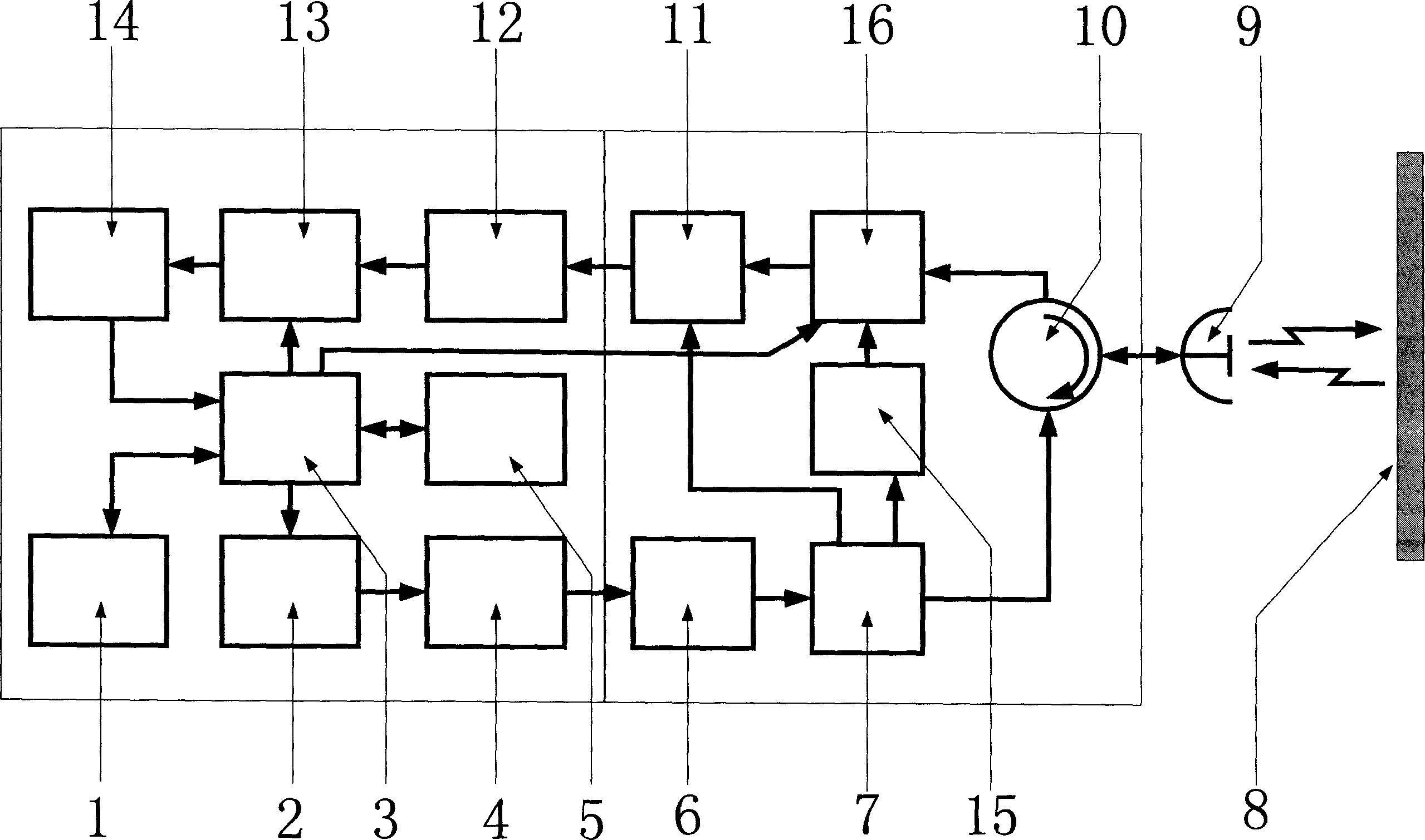
[0056] Implementation mode 2 such as figure 2 As shown, a microwave delay line 15 and a microwave switch 16 are added inside the evolution-corrected linear frequency modulation radar level gauge. The microwave delay line 15 produces a certain delay to the microwave, which can simulate a fixed distance target signal, so it can realize online self-calibration . The digital signal processor 3 outputs a digital signal to the D / A converter 2, and converts it into a voltage signal, which forms the control voltage of the voltage-controlled oscillator 6 of the microwave unit through the buffer amplifier 4, and stimulates the voltage-controlled oscillator 6 to generate a frequency-modulated signal. The signal passes through the coupler 7 and is transmitted by the antenna 9 via the circulator 10. The coupler couples two signals at the same time. One is sent to the mixer 11 as a reference signal, and the other is sent to the microwave switch after a fixed delay through the delay line 15. 16...


PUM


Abstract

This invention relates to a non-linear correction method of linear frequency-modulated radar object meter, which belongs to signal process and automatic measurement technique field. It divides the frequency-scanning voltage curve of the control oscillator and uses frequency spectrum analysis to extract characteristics information and adopts principle of evolution computation to get the end point coordinates of the curve to form non-linear frequency-scanning curve to compensate the non-linear property of the control oscillator without measurement of high-frequency microwave signals or phase to generate the linear frequency-modulated signals with high linear property. It solves the problem of linear frequency-modulated radar non-linear property.

Description

1. Technical Field [0001] The non-linear evolution correction method of the chirp radar level meter of the present invention belongs to the technical field of signal processing and automatic measurement. Specifically, it uses spectrum analysis to extract characteristic information and adopts the principle of evolutionary calculation to solve the problem of non-linear chirp radar frequency modulation. 2. Technical background [0002] Linear continuous frequency modulation radar level meter has the advantages of non-contact, high resolution and wide media adaptability in material level measurement, and is widely used in various level measurement. Because the voltage-controlled oscillator used in the linear continuous wave frequency modulation radar is inherently non-linear, when a completely linear voltage is used for frequency modulation, the final output frequency signal will show non-linear characteristics. Due to the frequency offset, the frequency mixing After the beat signal ...

Claims


Application Information

Patent Timeline
IPC IPC(8): G01F23/22G01F23/284G01S7/40
Inventor 谢克明阎高伟谢刚夏路易
Owner TAIYUAN UNIV OF TECH
Why Eureka
Try Eureka