Test circuit and test method for earth resistance

A grounding resistance and testing circuit technology, applied in the direction of grounding resistance measurement, etc., can solve problems such as large errors, achieve the effects of improving accuracy, simplifying the testing process and workload, and solving high sensitivity

Inactive Publication Date: 2005-07-06
SHENZHEN COMPTON TECH
View PDF0 Cites 8 Cited by
  • Summary
  • Abstract
  • Description
  • Claims
  • Application Information

AI Technical Summary

Problems solved by technology

This measurement method is more convenient to operate. You only need to place the two jaws on the measured conductive wire for about 1 meter to get the result, bu

Method used


Image

  • Test circuit and test method for earth resistance
  • Test circuit and test method for earth resistance
  • Test circuit and test method for earth resistance

Examples


Embodiment Construction

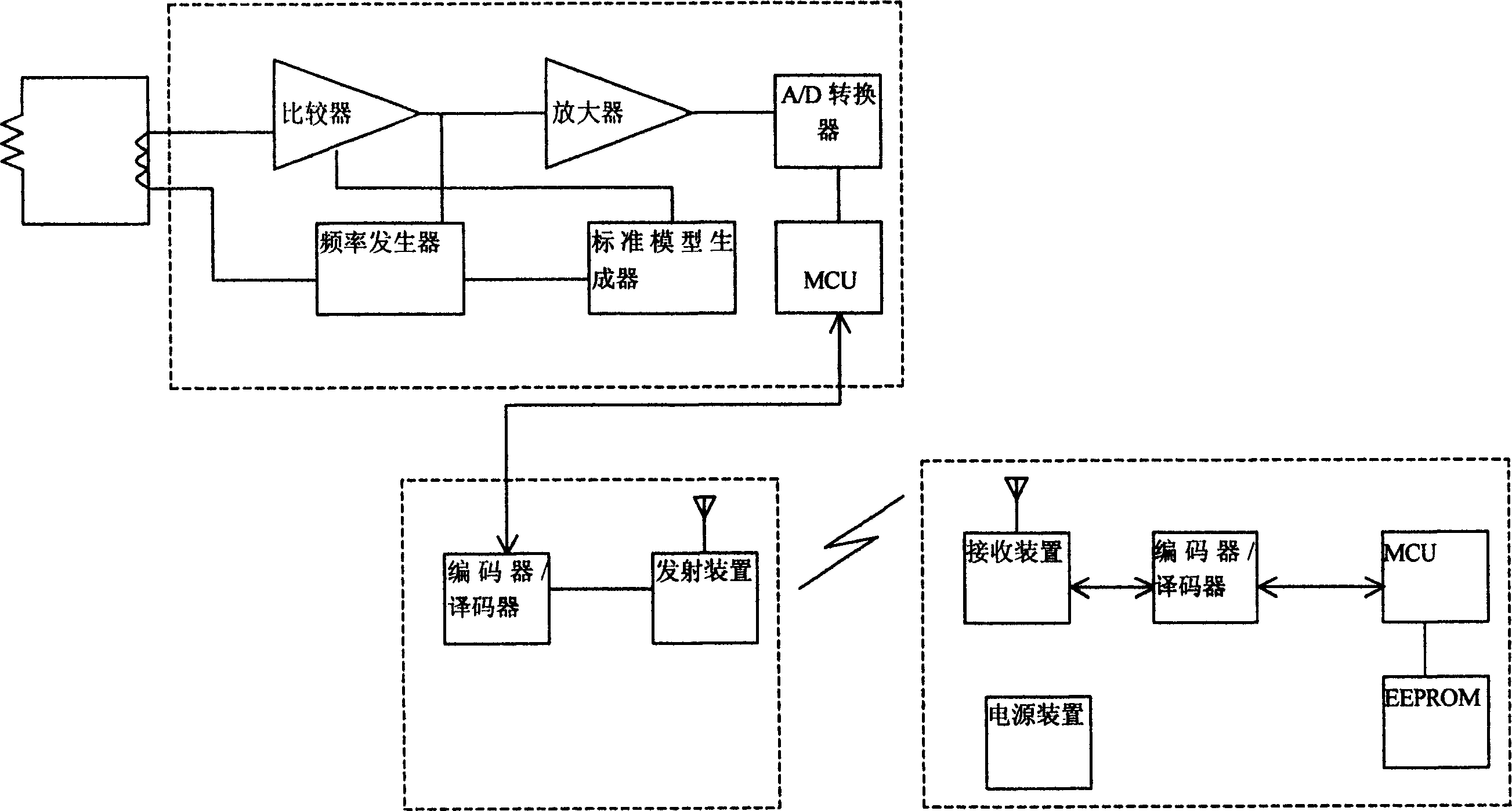
[0024] like image 3 Shown is the circuit principle block diagram of the present invention. The invention mainly includes a ground resistance testing unit, a testing result transmitting unit and a testing result receiving unit. Among them, the ground resistance test unit mainly includes a microprocessor, a frequency generator, a scanning power amplifier, a jaw coil, a standard model generator, a comparator and an A / D converter (analog-to-digital converter). The jaw coil is connected to both ends of the ground resistance to be measured, and can receive damping information of the ground resistance to be measured. The joint lead-out wire of jaw coil is respectively connected on frequency generator and comparator, and described frequency generator is used for generating scanning frequency; And can generate the standard model that is used for comparison in standard model generator, this standard model generator and The data obtained by the jaw coil will be compared with a certain...


PUM


Abstract

This invention relates to an earth connecting resistance measurement circuit, which mainly comprises earth resistance test unit composed of microprocessor, frequency generator, and scanning power enlarging part, clamp coil, standard model generator, comparer, and A/D converter. The said clamp coil is connected to both ends of resistance to be measured to receive the damp information of the resistance. The clamp coil joints leading part are separately connected to the frequency generator and comparer. The standard model generator is connected to the comparer and the enlarger is connected to the back of the comparer.

Description

technical field [0001] The invention relates to a ground resistance testing circuit and a testing method, in particular to a damping ground resistance testing unit and a testing method. Background technique [0002] The test of grounding resistance is a necessary step for electrical safety inspection and grounding project completion acceptance. The existing grounding resistance measurement widely adopts shaker-type power frequency resistance measuring instrument or impact resistance measuring instrument. Due to the large radius of the measuring electrode, it is difficult to measure in the environment of high urban building density, and the underground pipe network seriously affects the measurement accuracy. In addition, the imported clamp-type grounding resistance measuring instrument is expensive, and the measurement is greatly affected by the system. The reading and writing of test data must be sent back to the original manufacturer for data reading and writing, or a speci...

Claims


Application Information

Patent Timeline
IPC IPC(8): G01R27/20
Inventor 吴波林毅龙李利民
Owner SHENZHEN COMPTON TECH
Why Eureka
Try Eureka