Automatic-developing electromechanic planar array antenna

An automatic unfolding, planar array technology, applied in the directions of antennas, folded antennas, antenna parts, etc., can solve the problem that the whole machine cannot work quickly when entering the position, and achieves the effect of light weight, good adaptability and superior safety performance.

Active Publication Date: 2005-07-20
CHINA ELECTRONIC TECH GRP CORP NO 38 RES INST
View PDF0 Cites 11 Cited by
  • Summary
  • Abstract
  • Description
  • Claims
  • Application Information

AI Technical Summary

Problems solved by technology

[0003] The purpose of the present invention is to provide an automatic deployable electromechanical type that can automatically assemble / withdraw antennas in order to overcome the severe lag defects that the whole machine cannot work quickly when entering the position and cannot leave the position when it needs to be withdrawn due to manual assembly of antennas. planar array antenna

Method used


Image

  • Automatic-developing electromechanic planar array antenna
  • Automatic-developing electromechanic planar array antenna
  • Automatic-developing electromechanic planar array antenna

Examples


Embodiment Construction

[0027] The present invention will be further described through the embodiments below in conjunction with the accompanying drawings.

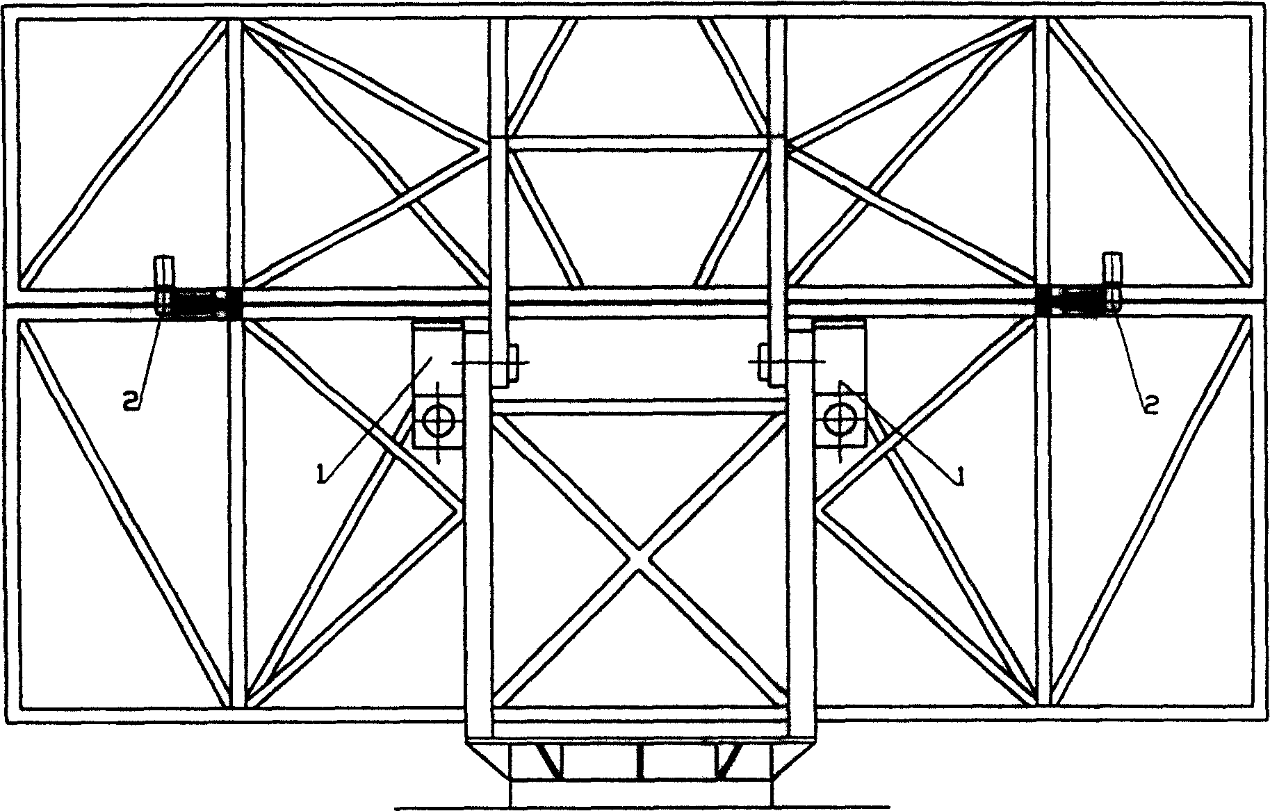
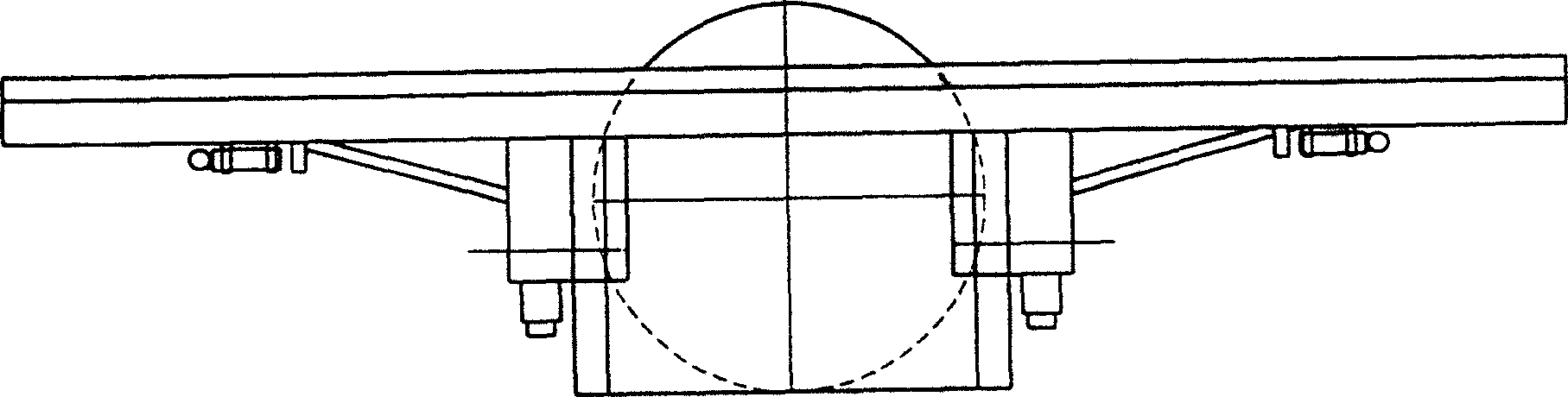
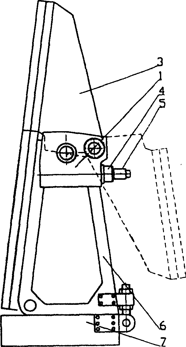
[0028] see figure 1 , figure 2 and image 3 , the automatically unfolding electromechanical planar array antenna includes a planar array antenna and a turntable 7, and the planar array antenna is divided into two fronts along the height direction, that is, the upper side block 3 of the antenna and the lower side block 6 of the antenna, and the upper front side is 7.4×1.6m wide. 2 , Weight 1600kg, lower front width 7.4X height 2.2m 2 , weighing 2500kg.

[0029] A pitch drive mechanism 1 is respectively installed symmetrically on the division planes of the upper and lower fronts on the back of the antenna. The pitch drive mechanism 1 includes a frame 8, a motor 5, a reducer 4, a sliding screw pair, and a crank slider sector gear mechanism. . The two ends of leading screw 9 are installed in the frame 8 through bearings, there are matching nut...


PUM


Abstract

The invention relates to wireless detecting device antenna that is called planar array antenna. Its feature is that pitching driving mechanism and electric lock mechanism is separately set on the splitting plane of the two array surfaces. The pitching driving mechanism includes frame, motor, reducer, sliding master screw, crank block segment gear mechanism. And the electric lock mechanism includes lock motor, reducer, master screw, nut and locating pin. The antenna can automatically open out and withdrawing. It has advantages like small volume, low weight, high reliability, stepless speed regulation, etc. And the temperature range it can be used is from 40 degree centigrade below zero to 55 degree centigrade.

Description

technical field [0001] The present invention relates to wireless detection equipment antennas, in particular planar array antennas. Background technique [0002] In recent years, high-mobility radars are mainly limited to radars with small-aperture antennas. With the development of electronic technology and the needs of modern warfare, the ground medium and long-range three-coordinate military radar has widely used planar array antennas, and is developing in the direction of high maneuverability and rapid response. The caliber of the medium and long-range three-coordinate radar antenna is too large, and the antenna must be divided into blocks to meet the performance requirements of cross-country transportation. If the automatic erection / withdrawal is not realized, the divided radar antenna will inevitably spend a lot of manpower and time to assemble the antenna after the radar enters the position, so that the radar will lose its rapid response capability. The planar array ...

Claims


Application Information

Patent Timeline
Patent Type & Authority Applications(China)
IPC IPC(8): H01Q1/00H01Q1/08H01Q3/02H01Q3/08
Inventor 陈建平倪仁品唐为民黄大革陈元元王庆虎
Owner CHINA ELECTRONIC TECH GRP CORP NO 38 RES INST
Why Eureka
Try Eureka