
Structure for controlling computer system executing speed and its method

A technology for controlling computer and execution speed, which is applied in program control devices, program loading/starting, software simulation/interpretation/simulation, etc., and can solve problems such as large memory spaces and inability to effectively improve efficiency of computer systems

Inactive Publication Date: 2005-08-03
INTERVIDEO DIGITAL TECH CORP
View PDF0 Cites 1 Cited by
  • Summary
  • Abstract
  • Description
  • Claims
  • Application Information

AI Technical Summary

Problems solved by technology

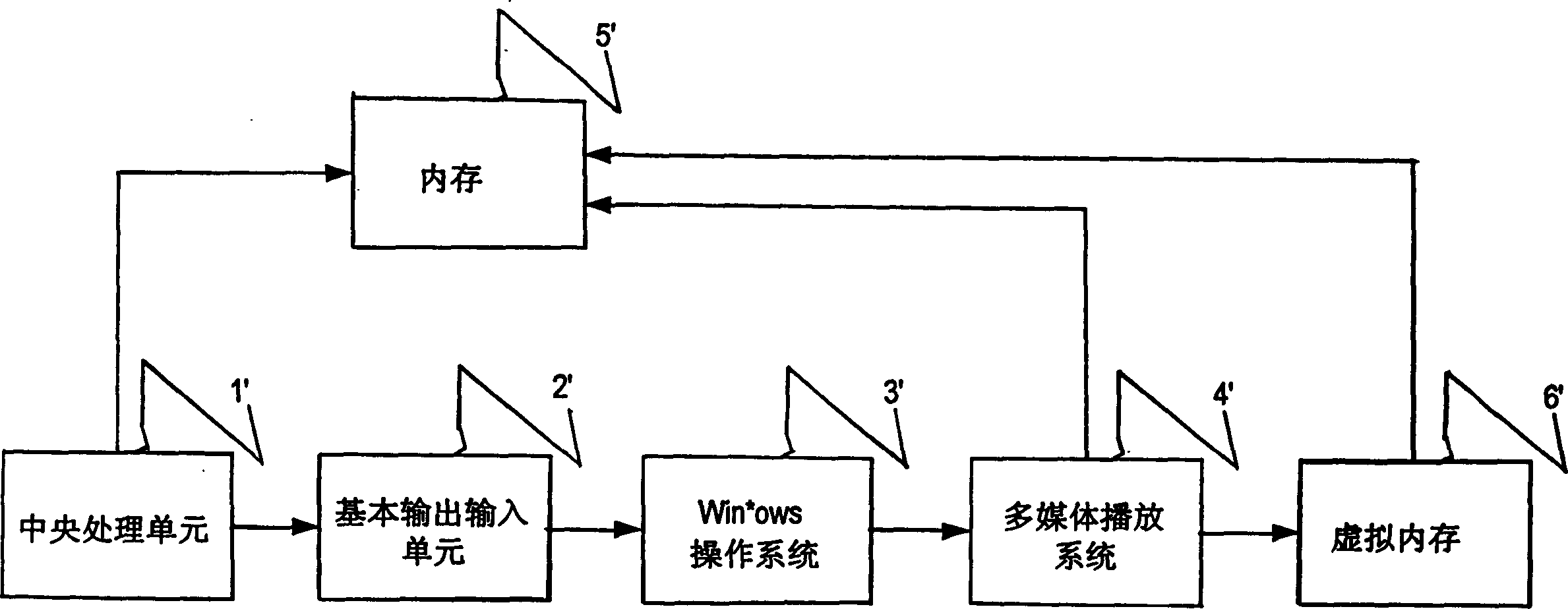
[0005] Although the memory capacity of the memory has been greatly improved, for the Windows operating system that is more commonly used on the market, because it is developed and supported by Microsoft, the world's largest software kingdom, it has various link libraries, drivers for peripheral devices, Human-machine interface, and application software, etc., have good technical support on each hardware chip or platform. In addition, it also provides easy deployment, management and use, enterprise-level reliability, usability compatibility and performance, Easily create dynamic corporate networks and Internet sites, speed up development with an integrated application server, and authorize users to perform multiple operations. Due to the high load of system resource consumption, users need to wait for a long time for the opening speed , the execution often occupies a lot of space in the memory. If other applications are executed, it is still necessary to use the storage device to emulate the memory to execute the application, so that the computer system still cannot effectively improve the efficiency of execution.

Method used

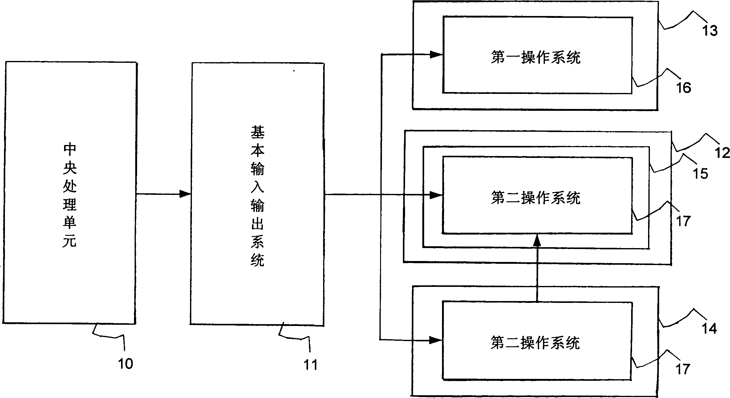

Image

  • Structure for controlling computer system executing speed and its method
  • Structure for controlling computer system executing speed and its method
  • Structure for controlling computer system executing speed and its method

Examples


Embodiment Construction

[0022] Below in conjunction with accompanying drawing, invention is described in further detail with preferred embodiment figure and configuration:

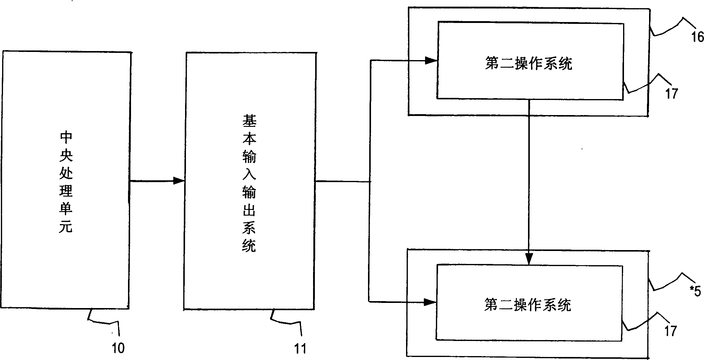
[0023] see figure 2 , which is a block diagram of opening the second operating system for a computer system of a preferred embodiment of the present invention, as shown in the figure, the present invention includes a central processing unit 10 for controlling the computer system; a basic input output system 11, It is used to control the boot settings of the computer system; a storage unit 13, which stores a first operating system 16; an external storage device 14, which stores a second operating system 17; and a virtual storage device 15, which It is a disk storage device emulating a partial area of ​​a memory unit 12. When the user turns on the power switch, the central processing unit 10 drives the basic input output system 11 to store the second operating system 17 in the external storage device 14 Load into the virtual stora...


PUM


Abstract

The present invention relates to the architecture and method of controlling computer system execution speed. The computer system includes one first operation system, one second operation system, one memory unit storing the first operation system, at least one information parameter and multimedia broadcasting system, and one CPU loading the second operation system. After the information parameter and multimedia broadcasting system is stored in one memory unit, the second operation system shares the information parameter and multimedia broadcasting system of the first operation system through one interface unit. Then, after one management unit detects the loading of the information parameter and multimedia broadcasting system in the memory unit, the memory unit is driven to a rest state, and this decreases the access of magnetic disc and speeds the execution speed of the computer system.

Description

technical field [0001] The present invention relates to a framework and method for controlling the execution speed of a computer system. By providing a memory unit with a large capacity, a central processing unit loads data parameters to be executed and a multimedia playback system into a storage unit. to execute in the memory unit, and drive the storage unit to a dormant state through a management unit, so as to reduce disk access operations and speed up the execution speed of the computer system. Background technique [0002] Based on the improvement of research and development technology, the memory specification has evolved from SDRAM to the current DDRRAM in order to provide more memory space and meet the needs of computer systems. [0003] Please refer to Fig. 1, which is a block diagram of a known storage device emulation memory, as shown in the figure, after a user activates the power switch of the computer system, a central processing unit 1 ' drives a basic input o...

Claims


Application Information

Patent Timeline
IPC IPC(8): G06F9/445G06F9/455
Inventor 吴东朋
Owner INTERVIDEO DIGITAL TECH CORP
Learn More