Bottle mouth cutting mechanism of automatic bottle blow molding machine

An automatic blow molding and bottle blowing machine technology, applied in metal processing, household components, household appliances, etc., can solve the problems of damage to the air supply pipe, damage to the tool, and complex overall structure, so as to eliminate movement errors and ensure cutting quality , the effect of simple overall structure

Active Publication Date: 2005-08-17
ZHANGJIAGANG TONGDA MACHINERY
View PDF4 Cites 21 Cited by
  • Summary
  • Abstract
  • Description
  • Claims
  • Application Information

AI Technical Summary

Problems solved by technology

In addition, bottles that need to be cut off must be conveyed by a special chain conveyor belt
[0004] The disadvantages of the above structure are: 1. It cannot be successfully docked with the blow molding machine, that is to say, it cannot be equipped or connected to the blow molding machine. It is a separate cutting device; 2. The overall structure is complicated and the operation is difficult. It is difficult to implement, because due to the large degree of freedom of movement of the bottle mouth, there are many unstable factors, and it is easy to cause irregular incisions and waste products, so it must be positioned by means of guide positioning rollers to form three stable fulcrums (two rollers) Disc knife) can be cut; 3. Using a conveyor belt to transport the bottle to be cut off the flash not only makes the whole device occupy a large space, but also cannot be reflected in the online flash removal on the blow molding machine
The applicant found that it also has the following deficiencies: one, it cannot be combined with the blow molding machine, and it is also an independent device, which cannot be reflected in the online cutting flash on the blow molding machine; the other is that it is formed by the cutting mechanism. The most important thing is extrusion cutting instead of rotary cutting, so in addition to extending a fixed head into the bottle mouth container of the hollow container to help support, it is also necessary to use a clamping piece to hold it, otherwise the bottle mouth will be deformed; second, every cutting After one action, the cutting arm needs to be opened and closed once, and the adjustment mechanism itself that enables the cutting arm to open and merge for up, down, forward and backward adjustment is relatively complicated; the third is to use a conveyor belt to feed the hollow container that needs to be cut off. Cutting by the cutting mechanism also makes the entire cutting device occupy a large space. Fourth, the overall structure is complex and uneconomical. For example, it is also equipped with a blower mechanism for blowing off the cut flash
One of the deficiencies of this technical solution also suffers from the defect that it cannot be organically formed as a complete whole with the blow molding and blow molding machine, because objectively it has not given the technical inspiration that it can be integrated with the blow molding and blow molding mechanism, For example, the waste parts separation mechanism relies on the bracket, and it cannot be linked with the inner and outer templates of the blow molding machine; the second is the action of the vacuum gripper clamping the hollow parts, and the action of the blowing mechanism blowing air into the hollow parts 1. The separation mechanism divides the action of removing waste parts into different stages. They cannot be synchronized with the action of the blow molding machine, so the work efficiency cannot be displayed; thirdly, because the moving distance of the tool’s withdrawal / insertion is determined by the supply It is determined by the gap between the air pipe and the shaft. When the moving distance of the tool is not adjusted properly, the air supply pipe will be damaged or the tool will be damaged by the air supply pipe. Fourth, only continuously supply air to the hollow part to ensure the air pressure in the hollow part. Therefore, due to the existence of an air supply mechanism, the structure of the whole device is complicated; fifth, it is difficult to guarantee the cutting quality of waste parts, because a pair of grippers (i.e. a bottle holding device) and a rack and a gear , hollow shaft, shaft sleeve, support arm, slider with cylinder liner, cutter and other components and set on a separate bracket The waste part separation mechanism (ie, the flash cutting device) is separated from each other, that is to say A pair of grippers and the waste parts separation mechanism cannot be synchronized and displaced equidistantly
In this way, the center of rotation of the tool cannot be aligned with the separation position on the hollow part held by a pair of grippers without error, which affects the cutting quality
Then, even if the waste part separation mechanism and a pair of grippers disclosed in the patent are reluctantly fitted to the automatic blow molding machine respectively, thereby formally showing the online cutting on the blow molding machine, but because the waste parts There is no structural connection between the separation mechanism and the gripper. Even if the original design can fully consider the design requirement that the matching error between the two is very small, however, in the actual use process, due to blow molding blowing The existence of the vibration factor of the bottle machine will cause vibration deformation, showing that the change error of the moving position of the waste part separation mechanism cannot correspond to the separation position on the hollow part clamped by the gripper.

Method used


Image

  • Bottle mouth cutting mechanism of automatic bottle blow molding machine
  • Bottle mouth cutting mechanism of automatic bottle blow molding machine
  • Bottle mouth cutting mechanism of automatic bottle blow molding machine

Examples


Embodiment 1

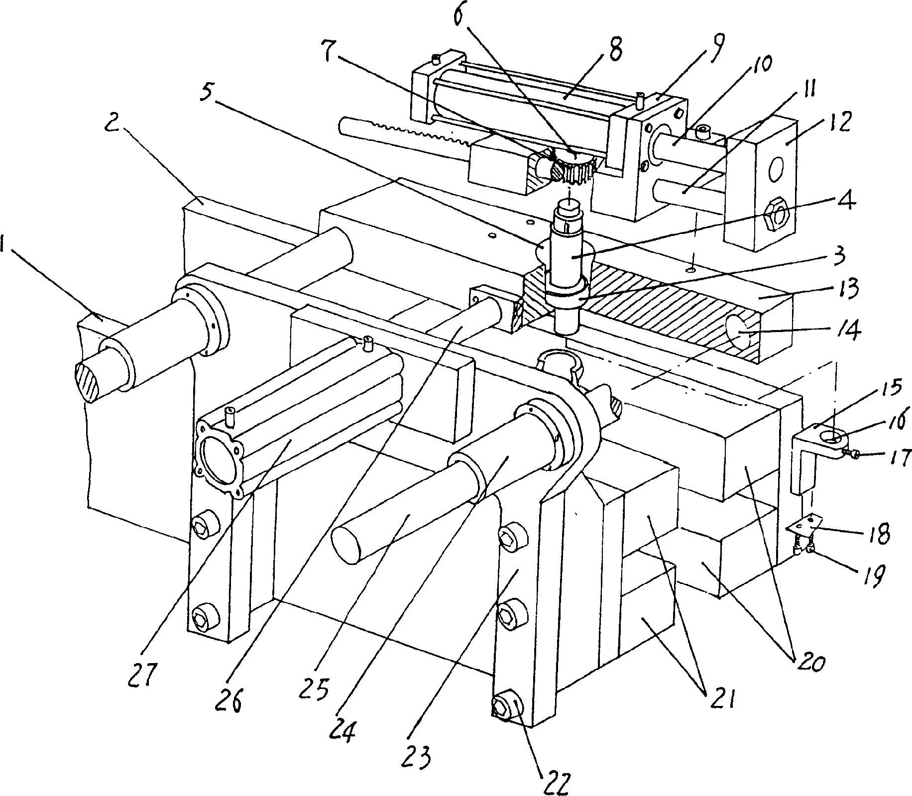
[0029] please see figure 1 and combine Figure 5 , the inner and outer mold connecting plates 2,1 of the bottle-holding device are respectively connected with the inner and outer templates 45,46 of the mold frame 42 of the automatic blow molding machine (see Figure 4 ), this connection can be realized with screws, or welding, etc. In this way, the inner and outer mold connecting plates 2,1 can be opened and closed with the opening and closing of the inner and outer templates 45,46 of the mold frame 42 of the automatic blow molding machine, and a pair of bottle half molds 20,21 face each other and can Dismountably be arranged on the inner side of a pair of inner and outer mold connecting plates 2,1, when the shape and specifications of the bottle 43 etc. change, then the bottle half molds 20,21 also change accordingly. figure 1 The bottle half-molds 20,21 shown in the illustration are only aimed at a certain kind of Figure 5 , Figure 8 For a bottle 43 of the specified si...

Embodiment 2

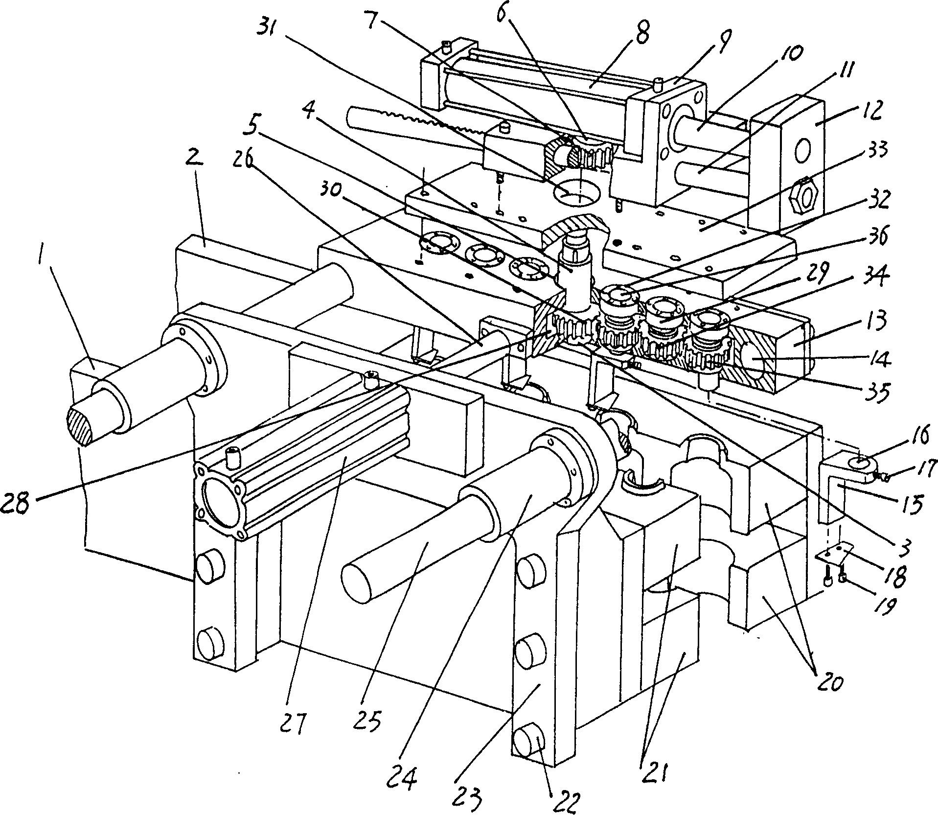
[0033] please see figure 2 and Figure 6 , the structure of this embodiment is an expansion of the structure disclosed in Embodiment 1. This expansion is mainly reflected in the change of the moving seat 13 and the central gear 30 is set at the lower end of the central shaft 4, and a moving seat 13 is formed. The hollow seat cavity 28 becomes a gear box-like structural form by arranging the corresponding components to be mentioned below, and the rest are still the same as in the first embodiment. There are also two groups of rotary cutter shafts 36 belonging to the flash cutting device on the mobile seat 13, and each group of rotary cutter shafts 36 has at least one pair, and a rotary cutter bar 15 is affixed to the bottom of each rotary cutter shaft 36. In this case, the lower end of the central shaft 4 may or may not be provided with the rotary cutter bar 15, and it is necessary to add a central gear 30. Two groups of rotary knife shafts 36 are shown in the figure, each g...

Embodiment 3

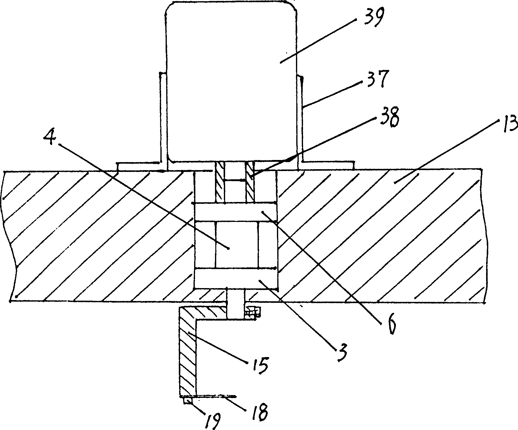
[0035] please see image 3 and Figure 7 , In this embodiment, the central shaft driving mechanism for driving the central shaft 4 to rotate is changed to adopt a stepper motor 39, and the rest are the same as in Embodiment 1 or 2. The stepping motor 39 is located on or claims to be seated on the moving seat 13 through a bracket 37, and the output shaft of the stepping motor 39 is connected with the central shaft 4 through a coupling 38, and the central shaft 4 is still supported by a pair of bearings 6,3. Realize being pivotally placed on the mobile seat 13. Compared with Embodiment 1 and Embodiment 2, the structure of this embodiment is simpler in structure and cheaper in cost.

[0036] Figure 8 It shows the situation after the bottle mouth burr 44 of the bottle 43 is cut off through the implementation of Examples 1, 2, and 3.

[0037] Applicants choose figure 2 , 6 and combine Figure 4 Describe the process that the present invention cuts off the bottleneck flash 4...


PUM


Abstract

The bottle mouth cutting mechanism as one auxiliary mechanism for automatic bottle blowing and molding machine includes one bottle holding device, one moving device and one bottle mouth flash edge cutting device. The bottle holding device is connected to one inner and outer mold plate pair capable of being opened and closed in the automatic bottle blowing and molding machine; the moving device is set on the bottle holding device; and the bottle mouth flash edge cutting device is set on the moving device and over the bottle holding device. The said structure makes the three parts of the bottle holding device, the moving device and the bottle mouth flash edge cutting device connected into one integral and this results in high cutting quality, simple integral structure and high cutting efficiency.

Description

technical field [0001] The invention relates to a bottle mouth cutting mechanism of an automatic blow molding blow molding machine, which plays the role of cutting off the process flash or process waste left on the bottle mouth after the bottle is blow molded, and is matched with the automatic blow molding blow molding machine. auxiliary agencies. Background technique [0002] It goes without saying that automatic blow molding blow molding machines are capable of efficiently blowing a variety of bottles. But, when blowing bottles such as jars, milk products bottles, etc., due to technological reasons, there are flashes on the mouth of the bottle after blowing. This flash is also called waste edge, which needs to be cut off. The traditional method of cutting the flash of the bottle mouth is to use manual cutting, which brings problems such as a lot of manpower, low work efficiency, and irregular incision; while the more advanced method is to use machine cutting, when the blo...

Claims


Application Information

Patent Timeline
Patent Type & Authority Applications(China)
IPC IPC(8): B26D3/16B29C49/04B29C49/42B29C49/72
CPCB26D3/166B29L2031/7158B29C49/74B29C2793/009B29C49/04B29C2049/6091
Inventor 徐文良
Owner ZHANGJIAGANG TONGDA MACHINERY
Why Eureka
Try Eureka