

Drive device for motor and air conditioner using same
A technology of motor drive and current detection device, which is applied in the direction of electronic commutator, single motor speed/torque control, application, etc., which can solve the problems of efficiency reduction and increase of motor iron loss, so as to improve work efficiency and reduce voltage Effect
- Summary
- Abstract
- Description
- Claims
- Application Information
AI Technical Summary
Problems solved by technology
Method used
Image

Examples
Embodiment 1
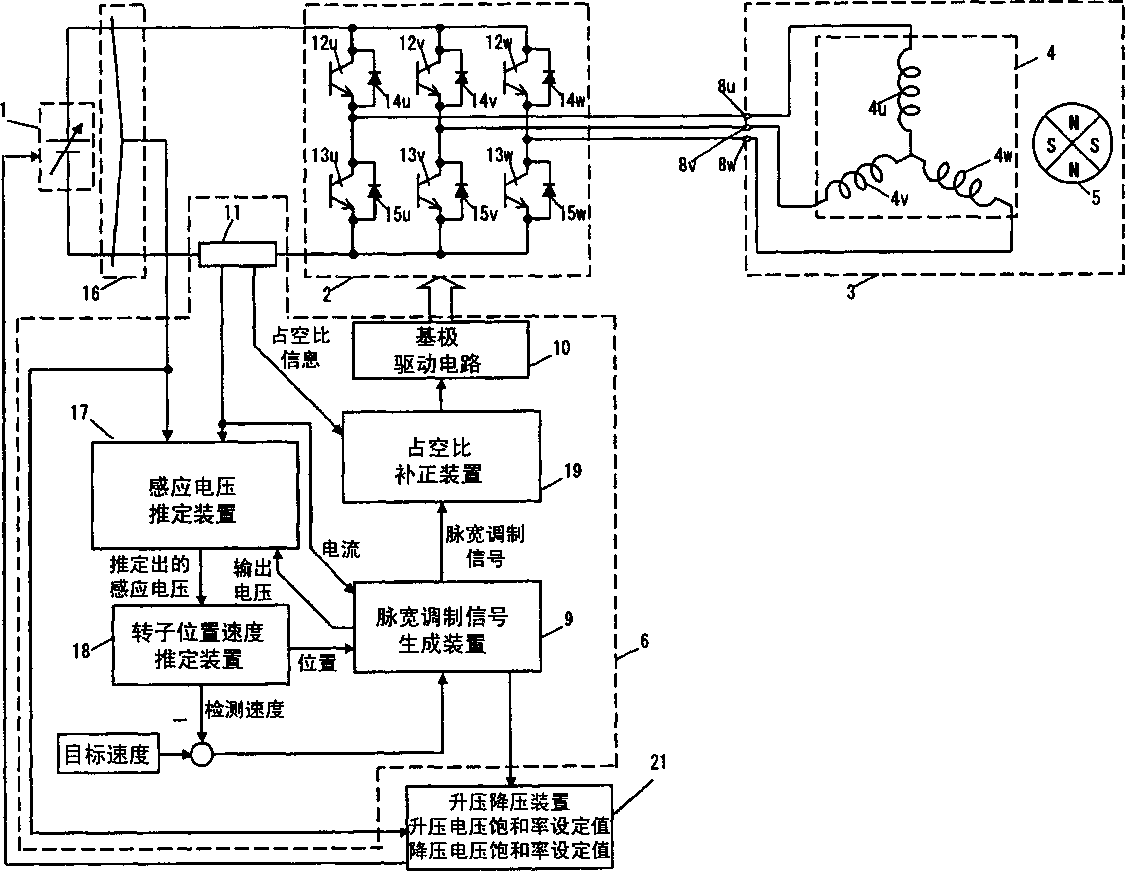
[0030] figure 1 It is a structural block diagram of the motor driving device in Embodiment 1 of the present invention. Among them, the DC voltage supplied from the variable DC power supply 1 is first converted into an AC voltage having a desired frequency and voltage by the inverter 2 , and then supplied to the brushless motor 3 . The frequency converter 2 is controlled on and off by a control part 6 .
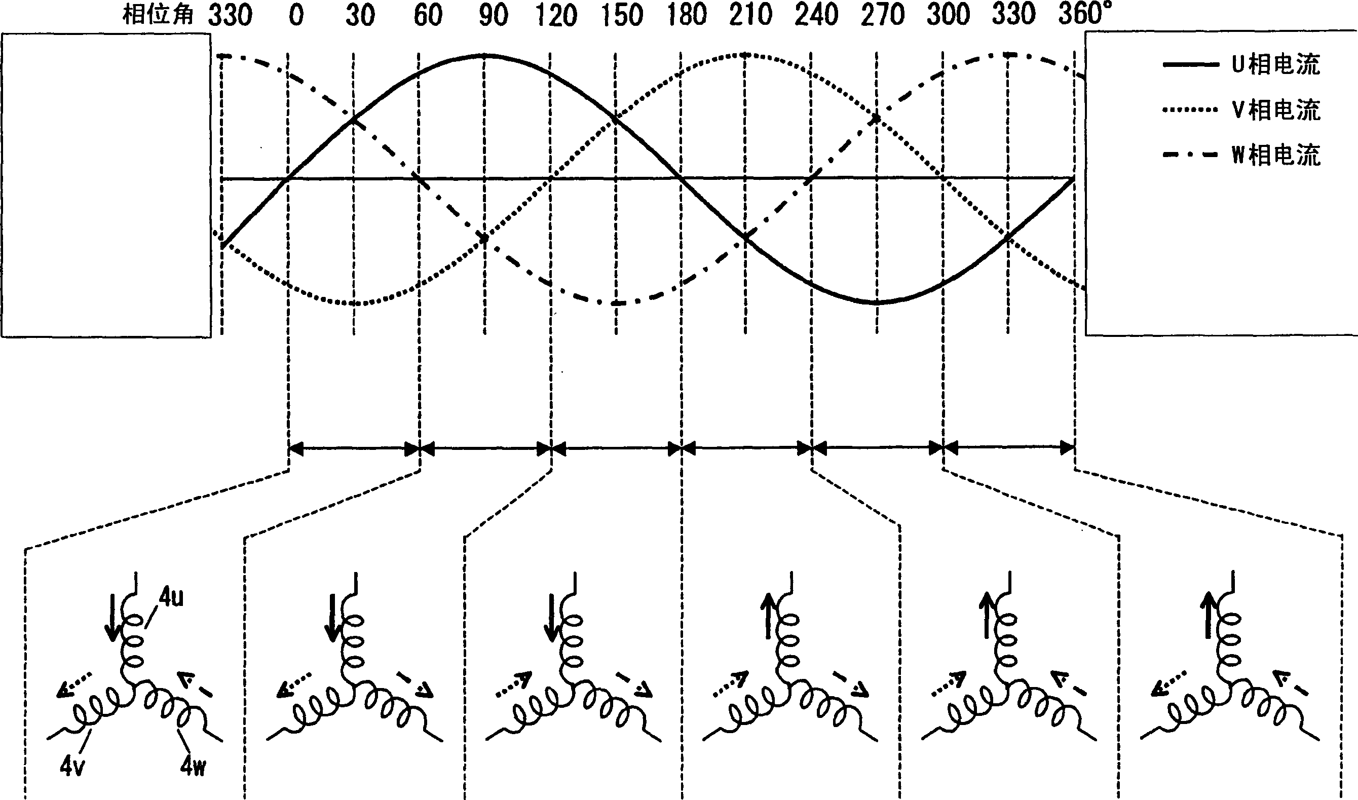
[0031] The brushless motor 3 is provided with a stator 4 and a rotor 5. The stator 4 is equipped with three-phase windings 4u, 4v and 4w connected in a Y shape around the neutral point, and the rotor 5 is equipped with magnets. U-phase terminal 8u is connected to a non-connecting end of U-phase winding 4u, V-phase terminal 8v is connected to a non-connecting end of V-phase winding 4v, and W-phase terminal 8w is connected to a non-connecting end of W-phase winding 4w.
[0032]The frequency converter 2 has three series circuits in which a pair of switching elements are respec...
Embodiment 2
[0110] In this example, in figure 1 The set value of the boost voltage saturation rate and the set value of the step-down voltage saturation rate are stored in the step-up and step-down device 21, which are determined by the rotational speed of the brushless motor 3 estimated by the rotor position and speed estimation device 18. switch. Specifically, in such switching based on the rotation speed, when the rotation speed of the brushless motor 3 estimated by the rotor position speed estimation device 18 is greater than a preset value, it is determined that the load of the brushless motor 3 is light, Even if the estimation error of the rotor position is larger, out-of-step is less likely to occur, so the set value of the boost voltage saturation rate and the set value of the step-down voltage saturation rate are increased. Since the variable DC power supply 1 is not prone to step-up, the high-efficiency working range of the motor can be expanded.
Embodiment 3
[0112] when figure 1 When the phase currents (iu, iv, iw) flowing in the windings of each phase detected by the current detection device 11 are very small, it can be concluded that the load of the brushless motor 3 is very light, and the estimation error of the rotor position will not appear even if it is larger. out of step. Therefore, in this embodiment, according to the phase currents (iu, iv, iw) flowing in each phase winding detected by the current detection device 11, the set value of the boost voltage saturation rate and the set value of the step-down voltage saturation rate are set to switch. In this way, the same effect can also be obtained.
PUM
 Abstract
Description
Claims
Application Information