Heat pump (refrigerating) system with injector and liquid storage subcooler

A subcooler and ejector technology, applied in the field of heat pumps, can solve the problems of increasing components and costs, increasing the number of faulty parts, reducing system energy consumption, etc., and achieves the effects of convenient processing and installation, wide operating conditions and high feasibility

Inactive Publication Date: 2005-08-24
BEIJING NEHT NEW ENERGY TECH DEV CO LTD
View PDF1 Cites 18 Cited by
  • Summary
  • Abstract
  • Description
  • Claims
  • Application Information

AI Technical Summary

Problems solved by technology

[0004] The above-mentioned technical solution still has obvious deficiencies. First, the heat pump system does not recover the pressure energy of the auxiliary refrigerant depressurization process to reduce the energy consumption of the system; It increases the components and cost of the system, and also increases the number of faulty parts of the system, reducing the reliability of operation.

Method used


Image

  • Heat pump (refrigerating) system with injector and liquid storage subcooler
  • Heat pump (refrigerating) system with injector and liquid storage subcooler
  • Heat pump (refrigerating) system with injector and liquid storage subcooler

Examples


Embodiment approach 2

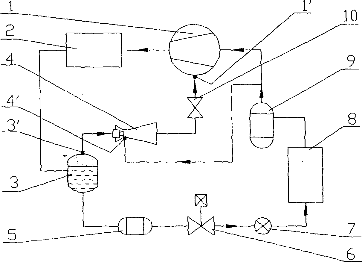
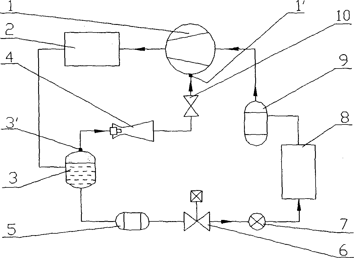
[0021] Embodiment 2 is similar to the heat pump system of Embodiment 1, see figure 2 . The difference is that the ejector 4 does not have an injection port 4 ′, that is, the ejector 4 does not eject the low-pressure refrigerant vapor at the outlet of the gas-liquid separator 9 or the evaporator 8 . The high-pressure refrigerant vapor at the outlet of the auxiliary circuit of the receiver subcooler 3 directly enters the ejector 4, expands and decompresses, and is sucked by the auxiliary air inlet of the compressor 1 through the stop valve 10. In this way, the heat pump system is further simplified, processing and installation are more convenient and costs are reduced.

Embodiment approach 3

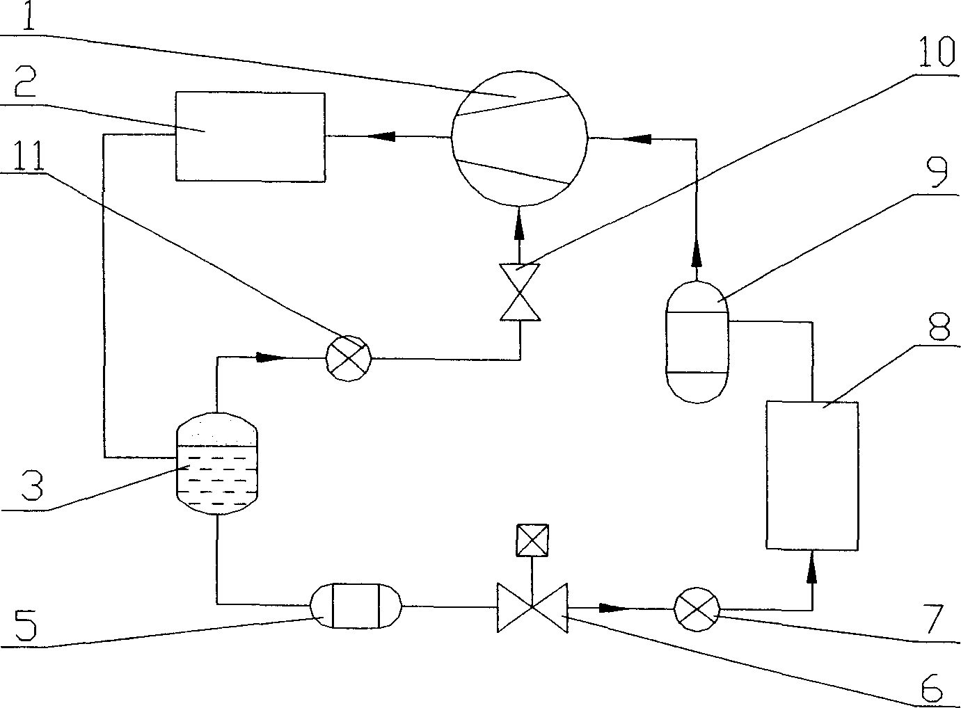
[0022] The heat pump system of embodiment 3 is similar to the heat pump system of embodiment 2, see image 3 . The difference is that the injector 4 is replaced by the auxiliary throttle element 11 . In this way, the high-pressure refrigerant vapor on the upper part of the receiver subcooler 3 directly enters the auxiliary throttling element 11 , and is sucked by the auxiliary air inlet of the compressor 1 after being reduced in pressure by the auxiliary throttling element 11 . In this way, the heat pump system is effectively simplified, and the structure is more compact, which is more conducive to processing and installation and reduces costs.

[0023] In the above-mentioned embodiments, conventional threaded connections or welding are used between the components, and conventional sealing rings are also used for the seals.


PUM


Abstract

A heat pump (refrigerating) system with ejecting device and liquor storing cooling device. It includes a main circuit consists of a compressor, a chiller, and liquor storing cooling device, ejector, flow restricting device and evaporator. The whole system is made up of the sealed main circuit and the aiding circuit. Between the sub-exit of the liquor storing cooling device and the sub air inlet port of the compressor in the main circuit an ejector is installed with the inducting ejecting port connected to the exit of the air liquor separator or evaporator,. The aiding circuit is made up of the ejector, compressor, chiller, and the liquor storing and cooling device. The high pressure steam of refrigerating medium is used as the working liquor of the ejector inducting the low pressure steam of refrigerating medium at the exit of the gas liquor separator and the evaporator. The ejector and the flow restricting device together enhance the utilization efficiency of the heat pump system. The liquor storing cooling device functions both as the liquor store and the cooling device.

Description

technical field [0001] A heat pump (refrigeration) system with an ejector and a liquid storage subcooler belongs to the technical field of heat pumps (refrigeration). Background technique [0002] Using an electric-driven heat pump system as a heating means for buildings to replace traditional coal / oil heating can greatly improve the energy utilization efficiency of winter heating, and can effectively reduce or eliminate the emission of pollutants into the atmosphere. Especially in central cities in colder climate areas, the effect brought by the use of electric heat pumps is particularly obvious. In order for the electric-driven heat pump system to operate stably and efficiently in cold weather conditions, it is required that when the heat pump generates a large temperature rise, its calorific value attenuation is small, the exhaust temperature of the compressor is stable and relatively low, and the energy utilization efficiency is high. higher. However, the traditional s...

Claims


Application Information

Patent Timeline
Patent Type & Authority Applications(China)
IPC IPC(8): F25B30/02
Inventor 马国远
Owner BEIJING NEHT NEW ENERGY TECH DEV CO LTD
Why Eureka
Try Eureka