
Electronic apparatus having cooling system, radiator thereof, and method for manufacturing thereof

A technology of electronic equipment and heat sink, applied in the field of electronic equipment, can solve the problems of complex manufacturing process, complicated manufacturing process, and manufacturing heat sink, etc., and achieve the effect that the shape is easy to change

Inactive Publication Date: 2005-08-24
HITACHI LTD
View PDF2 Cites 5 Cited by
  • Summary
  • Abstract
  • Description
  • Claims
  • Application Information

AI Technical Summary

Problems solved by technology

[0007] However, for the above-mentioned existing heat sinks, especially in the above-mentioned desktop personal computers and servers, etc., the heat sinks that are actually formed by installing fins for heat dissipation on S-shaped metal thin tubes are actually used. Chip installation and other reasons make the manufacturing process complicated and troublesome, so the price is also higher
In addition, in this existing heat sink, considering its structure, the overall appearance shape of the heat sink is generally plate-shaped or cubic-shaped, and it is difficult to manufacture it into a predetermined shape.
[0008] On the other hand, in the above-mentioned desktop personal computer or server, especially due to reasons such as the demand for miniaturization and space saving and the downward trend of its sales price in recent years, it is not necessarily possible to ensure the heat dissipation of the predetermined shape. sufficient space for the device, therefore, it is not necessarily possible to obtain the best cooling characteristics
On the contrary, there are often occasions where it must be forced into the small space left in the equipment box. In this case, it is not always possible to obtain sufficient cooling function from the radiator, and there is a problem that the characteristics of the liquid cooling system cannot be fully utilized.
In addition, in the above-mentioned prior art, due to its complicated manufacturing process, it is difficult to manufacture a heat sink with a freely deformable shape that can fit into the narrow space remaining in the box by a simple process.

Method used


Image

  • Electronic apparatus having cooling system, radiator thereof, and method for manufacturing thereof
  • Electronic apparatus having cooling system, radiator thereof, and method for manufacturing thereof
  • Electronic apparatus having cooling system, radiator thereof, and method for manufacturing thereof

Examples


Embodiment Construction

[0022] Hereinafter, embodiments of the present invention will be described in detail with reference to the drawings.

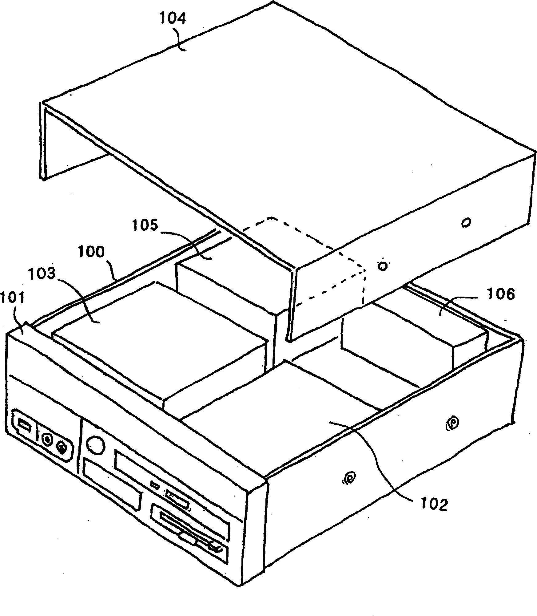
[0023] first, figure 2 An example of the overall configuration of an electronic device having a liquid cooling system according to an embodiment of the present invention is shown. In this example, for example, a case where the present invention is applied to the main body of a desktop personal computer is shown.

[0024] First, as shown in the figure, the main body of a desktop personal computer has a box 100 formed of a metal plate in a cubic shape, for example, and various switches including a power switch, connection terminals, indicator lights, etc. are provided on the front panel 101. , In addition, a drive device 102 for driving various external information recording media such as optical discs, CDs, and DVDs is arranged inside, and is opened toward the above-mentioned front panel portion 101 . In addition, reference numeral 103 in the figure shows a ...


PUM


Abstract

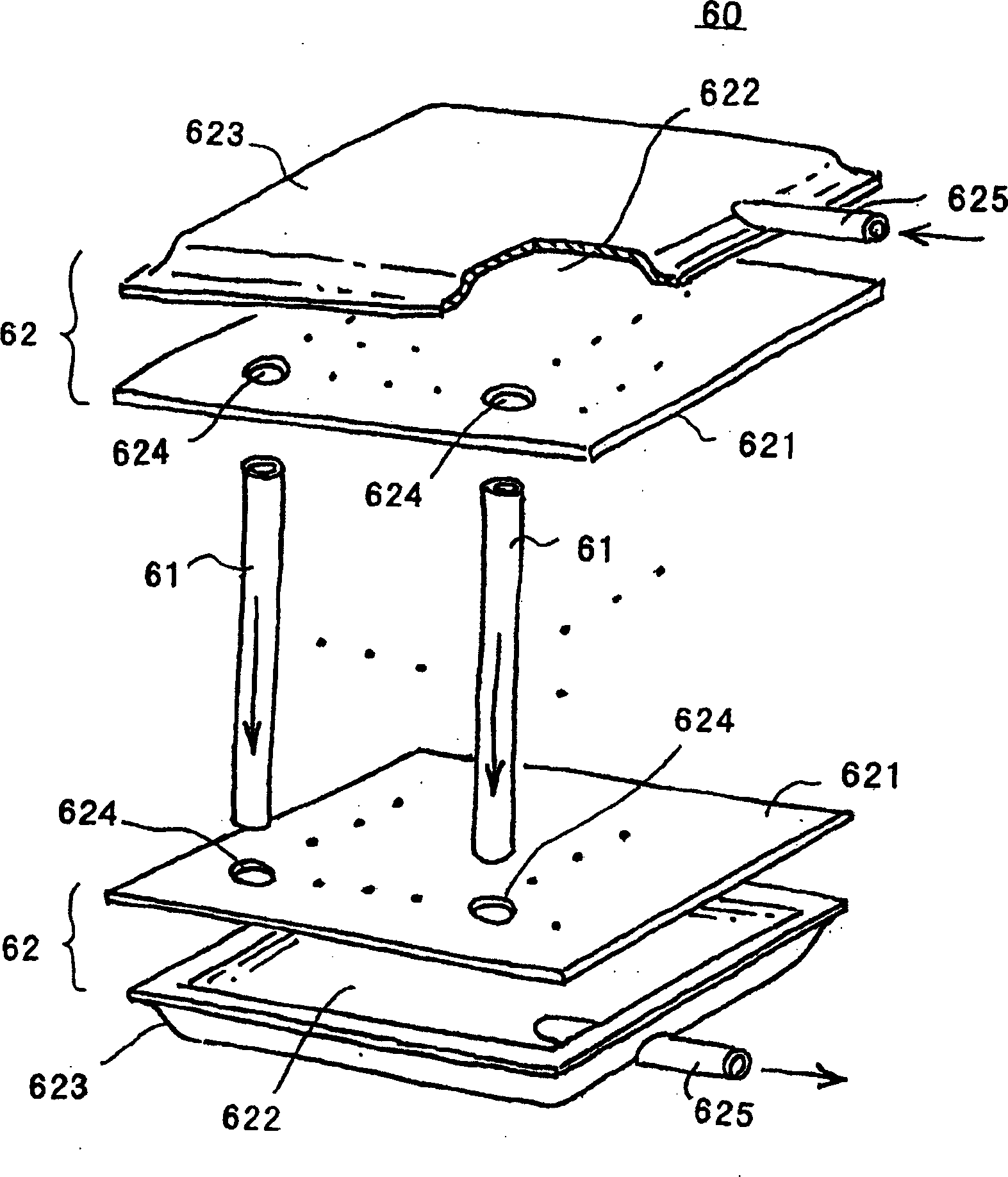
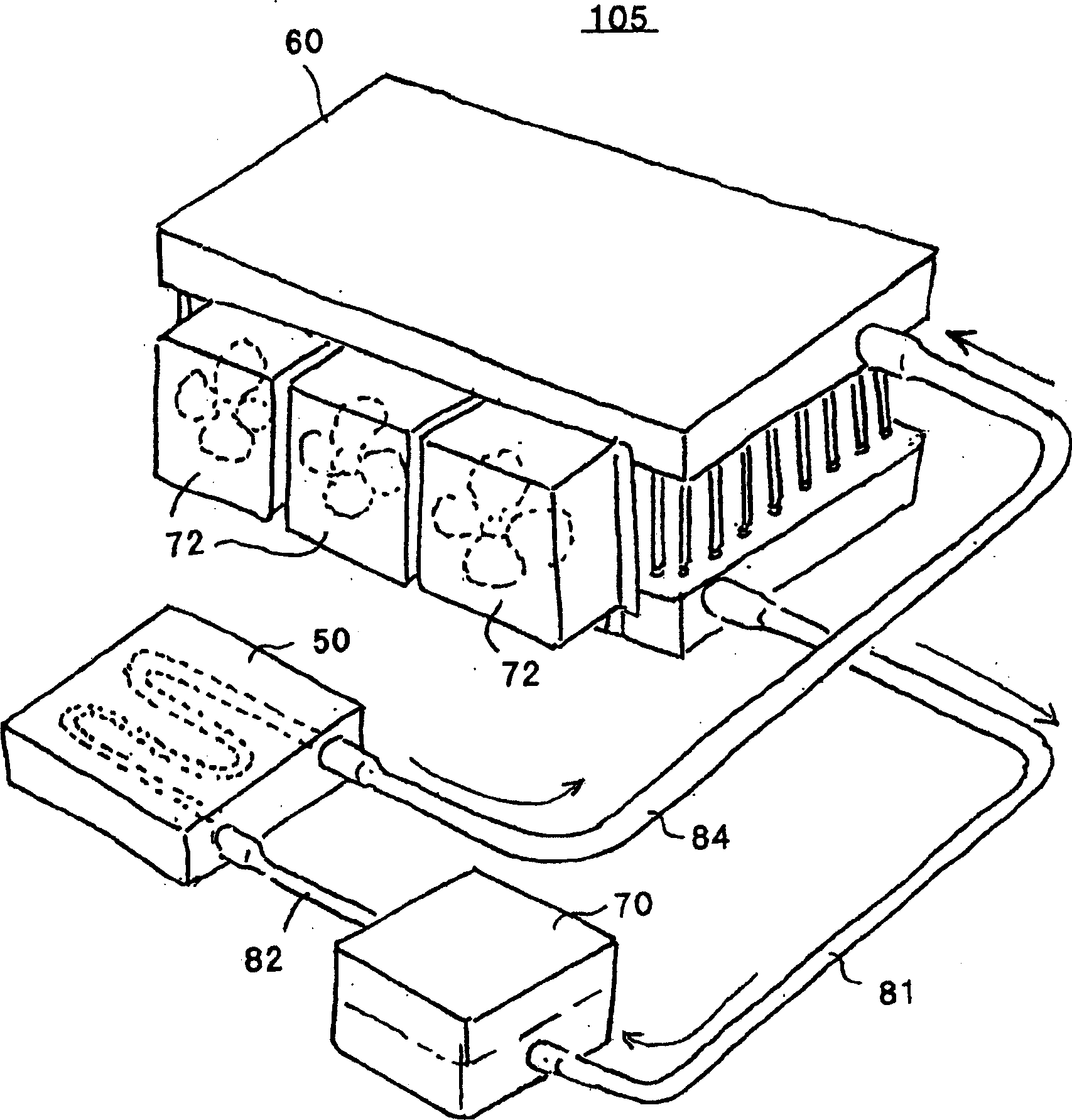
In an electronic apparatus having a liquid cooling system, and enabling optimal cooling characteristic for capacity with the aid of a radiator, which can be disposed or located fitting in a narrow space within a housing thereof, wherein a CPU (200) in need of cooling is installed within the housing (100), and the liquid cooling system for cooling the CPU comprises a cooling jacket (50) and a radiator (60)therein, wherein the radiator has a pair of headers (62) and (62), being constructed with disposing a large number of metal thin tubes (61,61...) there between, aligned in parallel to each other, and an outer configuration thereof can be changed easily and freely, and therefore it can be positioned even in the narrow space. Further, a cooling fan (64) or (66) for cooling the radiator (60) may be disposed therein, and in that case it is also possible to maintain a position for setting up a motor (65) or (67) for rotationally driving the fan, included therein.

Description

technical field [0001] The present invention relates to electronic equipment such as desktop personal computers and servers, and particularly to electronic equipment having a liquid cooling system capable of cooling semiconductor integrated circuit elements mounted inside as heat-generating elements more efficiently, and to electronic equipment suitable for use in The configuration of the heat sink used in the liquid cooling system and its manufacturing method. Background technique [0002] Semiconductor integrated circuit elements that are heating elements in electronic equipment such as desktop personal computers and servers, especially heating elements represented by CPUs (Central Processing Units), generally require cooling in order to ensure their normal operation. For this reason, conventionally, the cooling has been realized by using a heat transfer body integrally formed with fins called fins and a fan for blowing cooling air thereto. However, the continuous miniatu...

Claims


Application Information

Patent Timeline
Patent Type & Authority Applications(China)
IPC IPC(8): F25D9/00F25B21/02F28D1/053F28F9/18G06F1/20H01L23/473H05K7/20
CPCF28D2021/0029F28F9/182F28D1/05333G06F2200/201G06F1/20H05K7/20009B24B27/06B24B27/0007B24B23/08B23K31/02
Inventor 长桥繁男长绳尚南谷林太郎西原淳夫
Owner HITACHI LTD
Learn More