Heat elimination mechanism of electronic equipment

A heat dissipation mechanism and electronic device technology, applied in the direction of elastic/clamping device, circuit arrangement on the support structure, cooling/ventilation/heating transformation, etc., can solve the problems of fan power consumption, poor heat dissipation efficiency, and inapplicability

Inactive Publication Date: 2005-08-31
TAICHI HLDG
View PDF0 Cites 6 Cited by
  • Summary
  • Abstract
  • Description
  • Claims
  • Application Information

AI Technical Summary

Problems solved by technology

However, using a fan consumes power and also takes up space, which is not suitable for some electronic devices (such as thumb drives, wireless network cards, etc.)
However, if only heat dissipation holes are used, the heat dissipation efficiency is not good.

Method used


Image

  • Heat elimination mechanism of electronic equipment
  • Heat elimination mechanism of electronic equipment
  • Heat elimination mechanism of electronic equipment

Examples


Embodiment Construction

[0017] Some embodiments of the invention are described in detail below. However, the invention may be practiced broadly in other embodiments than those described in detail, and the scope of the invention is not limited except as defined by the appended claims.

[0018] In addition, in order to make the drawings show the features of the invention more concisely and clearly, the related drawings omit some connectors for external signal transmission, and also omit some mechanism parts not related to heat dissipation, and focus on explaining the structure of the heat dissipation mechanism.

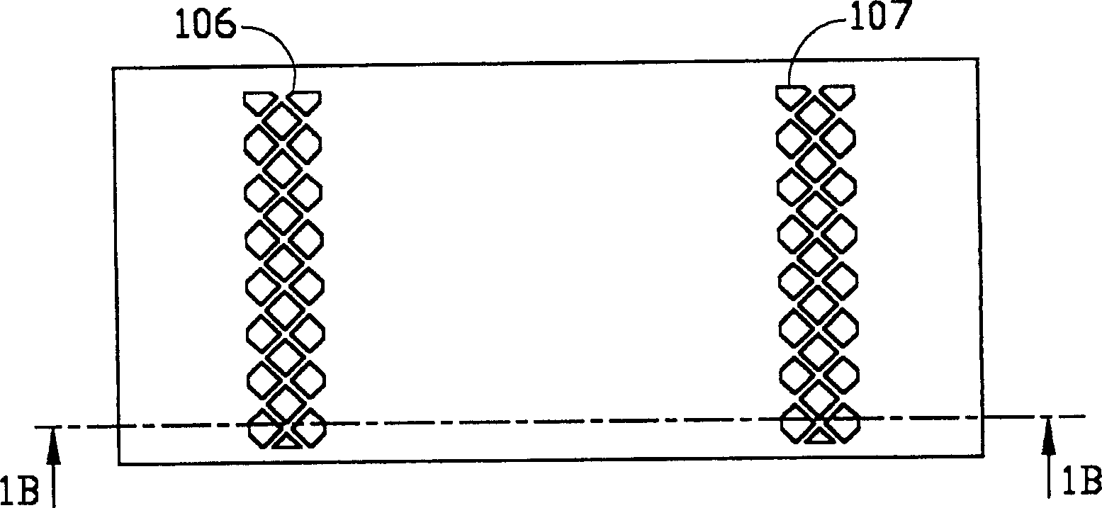
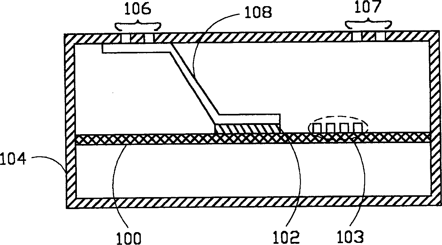
[0019] Figure 1A and Figure 1B It is an external view of a preferred embodiment of the heat dissipation mechanism of the electronic device disclosed in the present invention and a cross-sectional view viewed from the 1B-1B section. At least one heating element 102 is fixed on the substrate 100 , which is the main source of heat generation in the electronic device, and includes other element...


PUM


Abstract

One end of heat conducting sheet metal is connected to heating unit in electronic equipment; and the other end of the heat conducting sheet metal is jointed to opening hole area on case for heat radiation. Heat is dissipated thought the opening hole. The heat radiation mechanism is also suitable to small and portable electronic equipment to solve issue of not easy to radiate heat in small type electronic equipment effectively.

Description

technical field [0001] The invention relates to a heat dissipation mechanism, in particular to a heat dissipation mechanism which utilizes a heat conducting metal sheet to conduct heat energy to the outside of an electronic device for heat exchange. Background technique [0002] Some electronic device components, such as the central processing unit in the computer, the north bridge chip, etc., will generate a lot of heat due to the impedance consumption of electrical energy during the transmission or processing of electrical signals. If the heat is not effectively dissipated, it will affect the performance of the electronic device. Performance, loss of service life, what's more, it will be damaged and unusable. Therefore, if an electronic device has the above-mentioned elements that generate a large amount of heat energy, the heat dissipation problem must be considered during design to ensure the operating performance of the device and prolong the life of the device. At pre...

Claims


Application Information

Patent Timeline
Patent Type & Authority Applications(China)
IPC IPC(8): G12B15/06H05K7/12H05K7/20
Inventor 吴忠儒
Owner TAICHI HLDG
Why Eureka
Try Eureka