
Compact high power LED array

A LED array, high-power technology, applied in lighting devices, cooling/heating devices of lighting devices, light sources, etc., can solve problems such as redundancy, difficulty in removing fan noise, gap between shockproof performance and working stability, etc. The effect of uniform distribution, small lateral thermal resistance and simple structure

Inactive Publication Date: 2005-09-07
TSINGHUA UNIV
View PDF0 Cites 30 Cited by
  • Summary
  • Abstract
  • Description
  • Claims
  • Application Information

AI Technical Summary

Problems solved by technology

First of all, the life of the fan is limited, and there is a huge gap between the shockproof performance and the working stability of the LED, so the LED lighting device that uses the fan cooling must have a serious performance bottleneck on the fan, and the life of the LED itself is long. , work stability and other advantages are difficult to play
In addition, the noise of the fan is difficult to remove, and it cannot be used in environments that require high noise control, such as indoors.
Finally, air cooling will inevitably require corresponding equipment to cause air flow, which will make the entire lighting device bulky and redundant, limiting its application in some portable lighting products

Method used


Image

  • Compact high power LED array
  • Compact high power LED array
  • Compact high power LED array

Examples


Embodiment approach 1

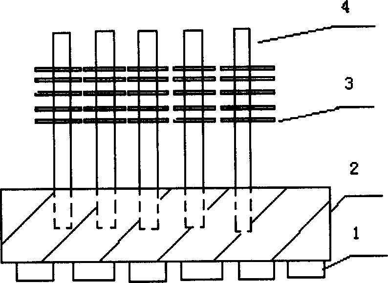
[0028] Embodiment 1 adopts a gravity heat pipe. from figure 1 It can be seen that the system consists of four parts. For the present invention, the extensibility of the heat sink and the bottom plate is conducive to the close contact with the heat pipe, so aluminum is used to make the device.

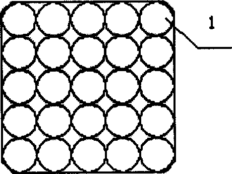
[0029] First, align the bottom plate and heat sink plate, and drill holes in the corresponding positions of bottom plate 2 and heat sink plate 3. The holes on the bottom plate are not opened through, and the hole depth is about half of the thickness of the bottom plate. Drill and tap screw holes on the lower surface of the bottom plate. Insert the heat pipe into the heat sink and solder the contacts together. Fix the LED 1 on the lower surface of the bottom plate. Insert the heat pipe with heat sink at one end into the hole on the upper surface of the LED base plate and solder them together.

[0030] Figure 4 It is a side view of the second embodiment of the present invention

Embodiment approach 2

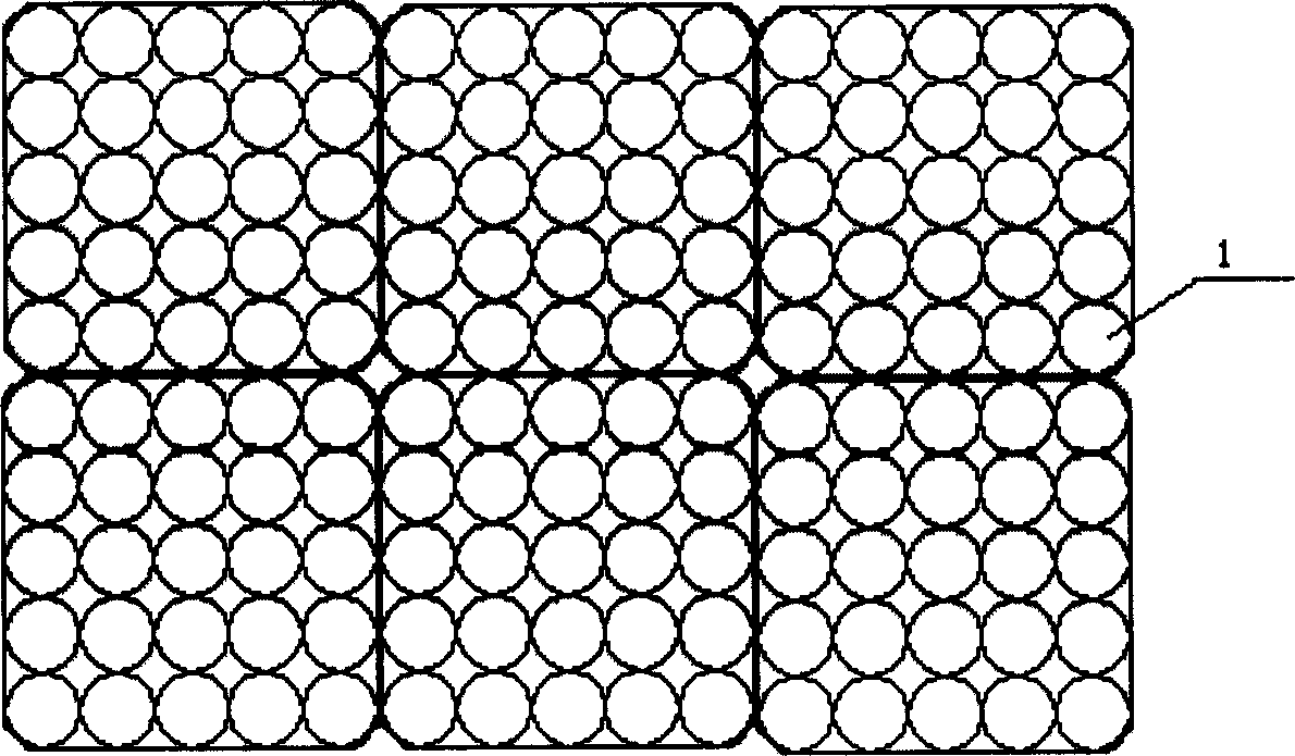
[0031] The posture of the heat pipe in Embodiment 2 is different from that in Embodiment 1. First bend the heat pipe to a certain angle. Drill holes horizontally on the bottom plate. Drill holes on the heat sink, the same as method 1. The assembly process is also the same as in method 1, as shown in the figure. Compared with method 1, method 2 has a better heat dissipation effect, because the contact between the bottom plate and the heat pipe is more sufficient. However, the disadvantage of the second method is that the two-dimensional splicing is not convenient, and it is more suitable for strip light sources.

[0032] The number of heat sinks in the two schemes is the same. For a LED of about 100W, the effective area of ​​the heat sink is 3000cm2, and it can work normally under natural cooling. The whole lamp provides a luminous flux of about 2000lm.


PUM


Abstract

The invention relates to a compact high power LED array that belongs to light emitting diode application technology field. Several LED array units assemble the light plat, and every LED array unit has base board that the thickness reaching several centimeters and is made up of high thermal conductivity material. It is the positive clan type LED fixed on baseboard. And the clan type heat pipe is inserted into the back or side surface of the baseboard and fixed on the cooling plate of the hot pipe condensation end. The baseboard temperature of the invention is equal, and the system thermal resistance is low. It can sustain over one hundred LED working steadily.

Description

technical field [0001] The invention relates to a compact light-emitting diode array, which belongs to the application technical field of light-emitting diodes. The invention is suitable for home indoor lighting, outdoor landscape lighting, city farewell lighting and the like. Background technique [0002] The invention is developed from high-power LED and heat pipe cooling technology. [0003] So far, the luminous efficiency of LED is still relatively low, and about 90% of the energy consumed is converted into heat. The efficiency of low-power LED can be made relatively high, which can reach 70lm / W, but due to the low power, the total luminous flux is about 1lm, which cannot meet the lighting requirements of most occasions. The emergence of power LEDs has changed this situation to a certain extent, but its heat generation is greater. Currently, the brightness of a single high-power LED can only reach 160lm (lumileds Luxeon V star, Technical DataDS30), which cannot meet th...

Claims


Application Information

Patent Timeline
IPC IPC(8): F21K9/20F21V29/51F21V29/76F21Y115/10
Inventor 罗毅周长波杨毅韩彦军
Owner TSINGHUA UNIV
Features
  • Generate Ideas
  • Intellectual Property
  • Life Sciences
  • Materials
  • Tech Scout
  • Unparalleled Data Quality
  • Higher Quality Content
  • 60% Fewer Hallucinations
Learn More