Convergent oscillation type demagnetization device

A damping and demagnetization technology, applied in the direction of magnetic objects, electrical components, circuits, etc., can solve the problem of insufficient wavenumber demagnetization magnetic field.

Inactive Publication Date: 2005-09-07
李志平 +1
View PDF0 Cites 6 Cited by
  • Summary
  • Abstract
  • Description
  • Claims
  • Application Information

AI Technical Summary

Problems solved by technology

The invention can solve the problem that the existing demagnetization device cann...

Method used


Image

  • Convergent oscillation type demagnetization device
  • Convergent oscillation type demagnetization device
  • Convergent oscillation type demagnetization device

Examples


specific Embodiment approach 1

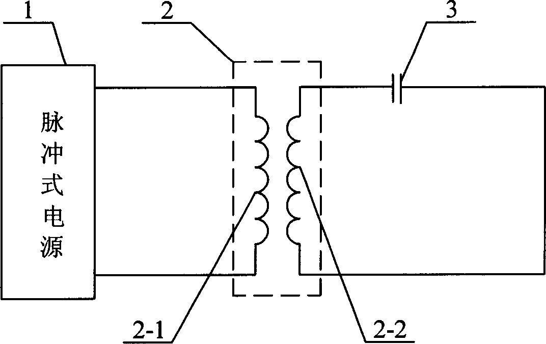
[0005] Specific implementation mode one: combine figure 1 Describe this embodiment, it is made up of pulse type power supply 1, mutual induction coil 2, capacitor 3; The ends are respectively connected to the two ends of the capacitor 3, and the first and the ends of the coil 2-1 are respectively connected to the two output ends of the pulse power supply 1. This embodiment enables the ideal demagnetization of the permanent magnets, magnetic powders and workpiece materials that need to be demagnetized in the mutual induction coil 2 . The front-end pulsed power supply 1 can be a specially designed pulsed power supply, or an existing pulsed magnetizing power supply can be utilized. The demagnetizing field in the mutual inductance coil 2 is also an ideal orientation magnetic field, which can be used for magnetic field orientation of powder and permanent magnetic material forming magnetic field orientation and demagnetization after orientation in the cavity or mold in the coil.

specific Embodiment approach 2

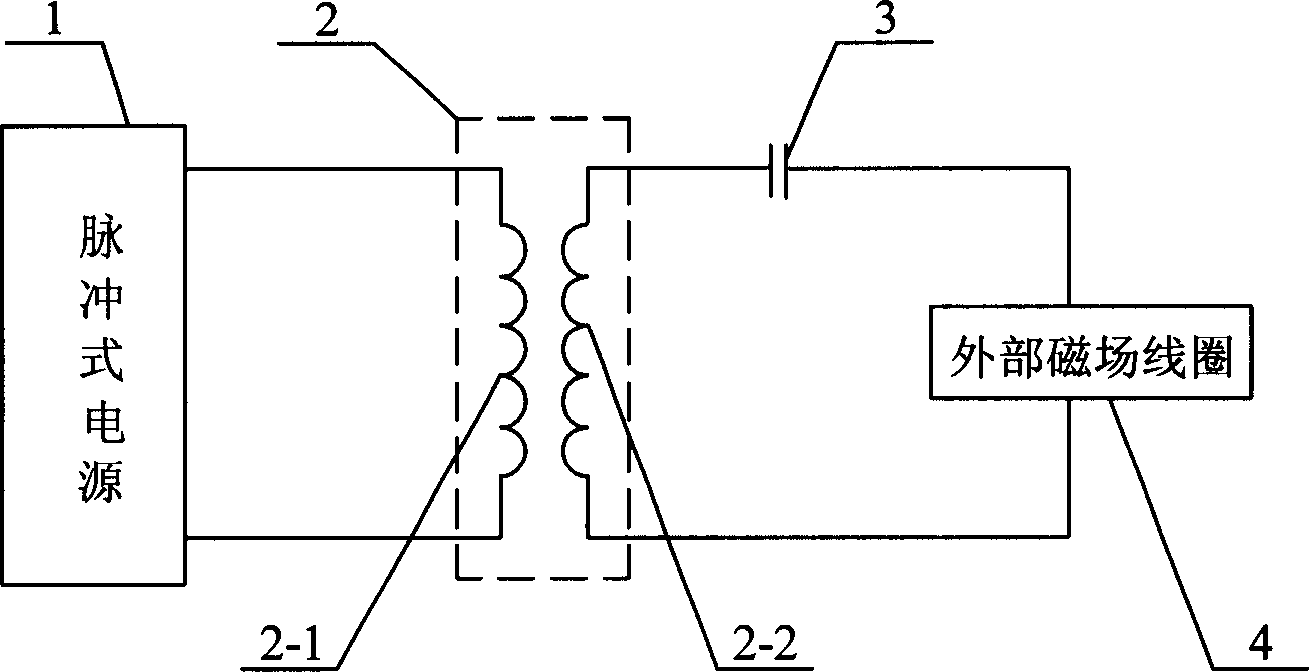
[0006] Specific implementation mode two: combination figure 2 Describe the present embodiment, present embodiment adds external magnetic field coil 4 on the basis of specific embodiment one; One end of external magnetic field coil 4 is connected with one end of coil 2-2, and the other end of external magnetic field coil 4 is connected with one end of capacitor 3, The other end of the capacitor 3 is connected to the other end of the coil 2-2; other components and connections are the same as those in the first embodiment. The external magnetic field coil 4 in this embodiment may be a solenoid or a magnetizing seat and coils of various structures including a multi-pole magnetizing seat. In this embodiment, the external magnetic field coil 4 is used to demagnetize the placed permanent magnets, magnetic powder and workpiece materials that need to be demagnetized.

specific Embodiment approach 3

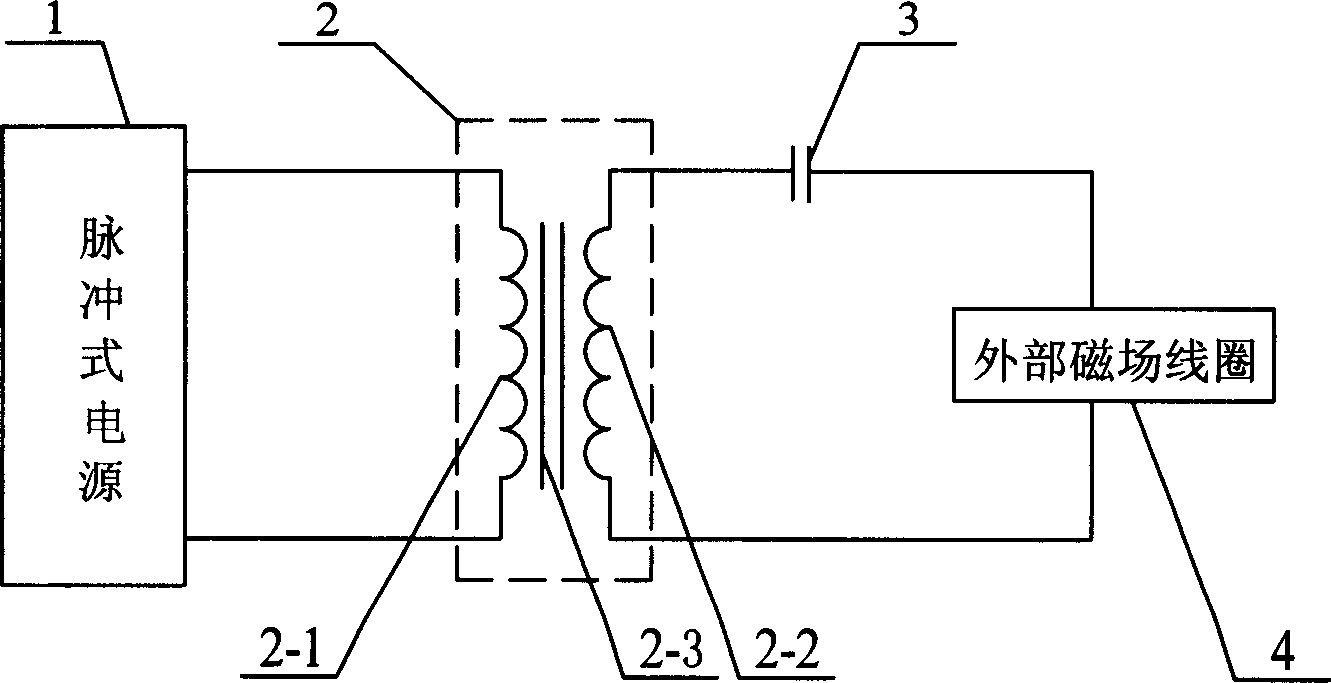
[0007] Specific implementation mode three: combination Figure 4 This embodiment will be described. On the basis of Embodiment 1, this embodiment adds an external magnetic field coil 4 ; the external magnetic field coil 4 is connected in parallel with the capacitor 3 . Other compositions and connections are the same as in the first embodiment. The external magnetic field coil 4 may be magnetizing seats and coils of various structures including multi-pole magnetizing seats.


PUM


Abstract

The invention discloses a damping oscillation-type demagnetizing device, relating to the field of demagnetizing technique, and comprising mutual inductor and also pulse power supply as well as capacitor; wherein, the mutual inductor is a hollow mutual inductor, coiled of a primary coil and a secondary coil; and two ends of the secondary coil are connected with those of the capacitor, respectively, and two ends of the primary coil are two output ends of the pulse power supply, respectively. The invention can obtain a demagnetizing filed with enough wave number and reduction rate to completely demagnetize permanent magnet; the oscillation of the invention happens in the secondary loop, unable to be affected by high-capacity energy storage capacitor, thus obtaining idealized free damping oscillation magnetic field; and the structure of the invention is simple, and the invention is convenient to use and easy to maintain.

Description

Technical field: [0001] The invention relates to the technical field of demagnetization, in particular to a damped oscillation type demagnetization device. Background technique: [0002] The existing pulse charging and demagnetizing device is composed of a pulse power supply and a solenoid coil or a magnetic field coil fixture of other structures. It is used to magnetize the permanent magnet material by using the magnetizing current provided by the pulse power supply to generate a magnetic field in the solenoid coil or other magnetic field coil fixtures; it is used to control the direction of the current in the helical coil when demagnetizing. A positive and negative alternating magnetic field is generated in the tube coil to demagnetize the permanent magnet material. Demagnetization is to demagnetize the permanent magnet material through the electronic switch to control the current to alternate positive and negative successively and gradually decrease to obtain the demagne...

Claims


Application Information

Patent Timeline
IPC IPC(8): H01F13/00
Inventor 李志平
Owner 李志平
Why Eureka
Try Eureka