
Patsnap Eureka
For R&D, Patsnap Eureka makes reading and utilizing patents & technical documents easy.
Patsnap Eureka AIR
Designed for self-driven R&D workflows. Generate viable solutions, solve complex R&D challenges, empower your innovation with AI.

Patsnap Eureka Materials
Designed for material experts only. Revolutionize your material R&D, from search, analyze, to developing new materials.

TechResearch
Generate reliable direction feasibility study reports for your R&D in just a few steps.

TechSeek
Discover and master advanced knowledge NOW. Basics, ideas, possibilities, all at once.

TechMind
As an expert in R&D Theories, TechMind can generates customized viable solutions instantly.

TechRisk
Analyze your overall solution with one click, know your potential R&D risks in advance.

TechMonitor
Get weekly tech updates, stay abreast of the latest tech innovations and key insights.
Cathode-ray tube apparatus
A technology for cathode ray tubes and tube shafts, applied in the direction of cathode ray tubes/electron beam tubes, electrode devices and related components, discharge tubes, etc., can solve problems such as impossibility and unevenness
- Summary
- Abstract
- Description
- Claims
- Application Information
AI Technical Summary
Problems solved by technology
Method used
Image

Examples
Embodiment Construction
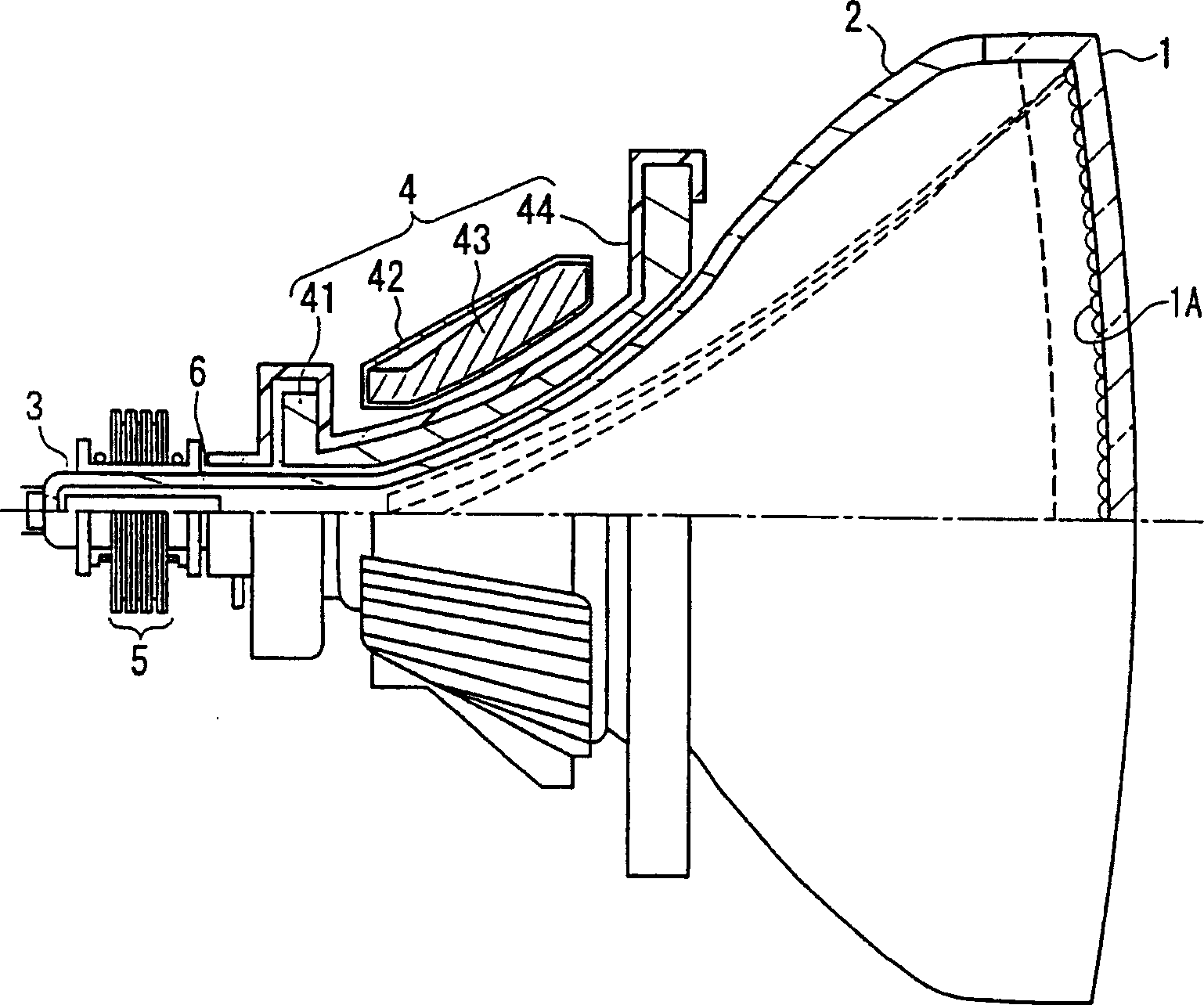
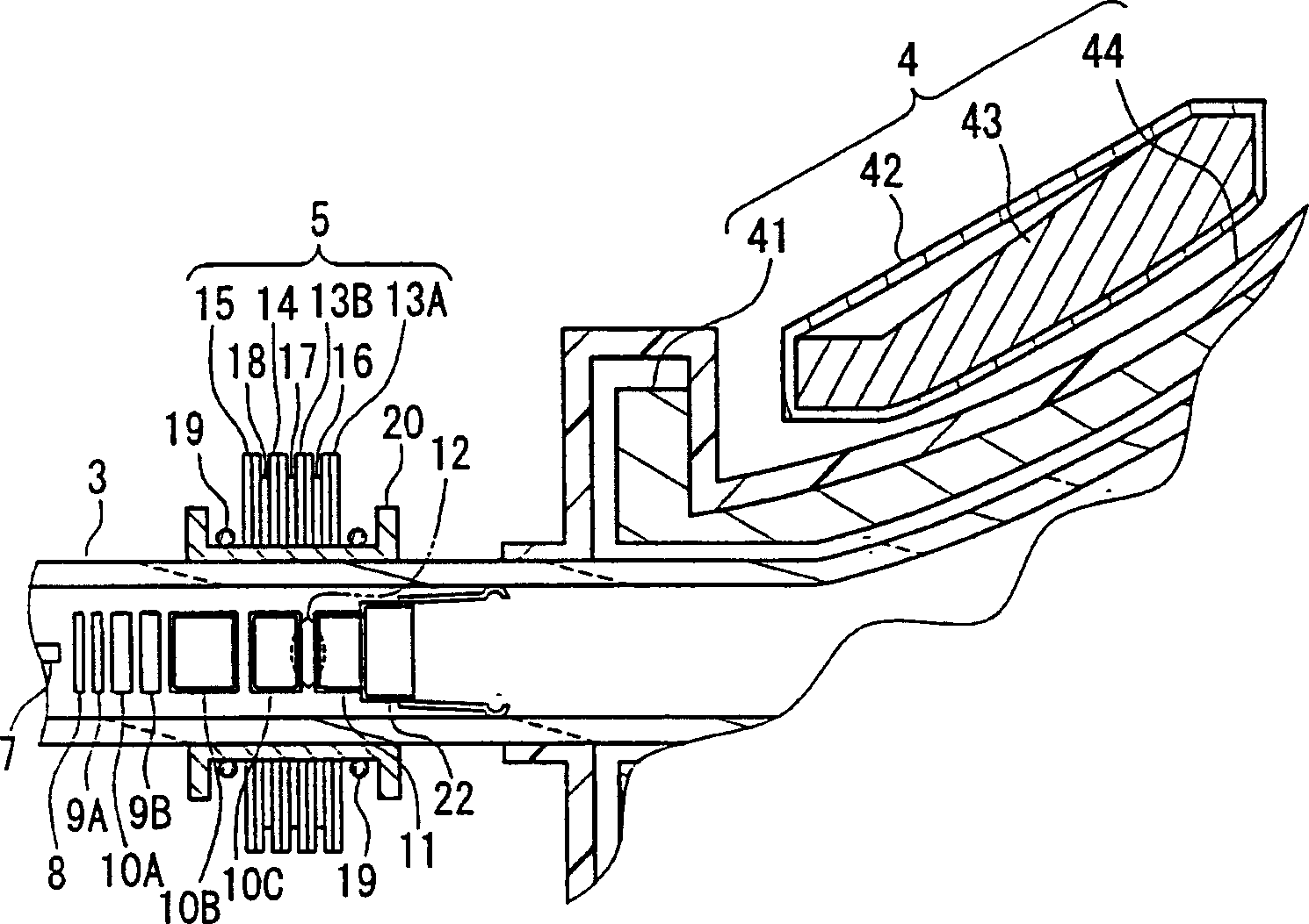
[0019] According to the first and second cathode ray tube devices of the present invention, a spacer made of a magnetic body is placed between the magnetic rings of the CPU. Therefore, the magnetic flux density of the speed modulation coil can be increased, and the speed modulation sensitivity can be enhanced without disturbing the magnetic field of the magnetic ring of the CPU and without increasing the number of components. Thus, image quality can be significantly improved. Furthermore, the spacer made of a magnetic body does not affect the operation of correcting the degree of convergence performed by adjusting the rotation phase of the magnetic ring, so that a satisfactory degree of convergence is easily obtained with the magnetic ring.
[0020] Furthermore, in the first cathode ray tube device, at least one spacer is made of only one kind of magnetic body, so the spacer can be manufactured at low cost.
[0021] Furthermore, in the second cathode ray tube device, a non-me...
PUM
| Property | Measurement | Unit |
|---|---|---|
| diameter | aaaaa | aaaaa |
Abstract
Description
Claims
Application Information
 - R&D Engineer
- R&D Manager
- IP Professional
- Industry Leading Data Capabilities
- Powerful AI technology
- Patent DNA Extraction
Browse by: Latest US Patents, China's latest patents, Technical Efficacy Thesaurus, Application Domain, Technology Topic, Popular Technical Reports.
© 2024 PatSnap. All rights reserved.Legal|Privacy policy|Modern Slavery Act Transparency Statement|Sitemap|About US| Contact US: help@patsnap.com