Viscous damper

一种粘性阻尼器、惯性质量的技术,应用在弹簧/减震器、机器/发动机、发动机元件等方向,能够解决制造工艺复杂等问题,达到提高广泛应用性的效果

Inactive Publication Date: 2005-09-07
FUKOKU CO LTD
View PDF1 Cites 7 Cited by
  • Summary
  • Abstract
  • Description
  • Claims
  • Application Information

AI Technical Summary

Problems solved by technology

Therefore, since the cast inertial mass body needs to cut the surface, etc., it needs to be finished, and the manufacturing process is complicated.

Method used


Image

  • Viscous damper
  • Viscous damper
  • Viscous damper

Examples


Embodiment Construction

[0030] Hereinafter, embodiments of the present invention will be described in detail with reference to the drawings.

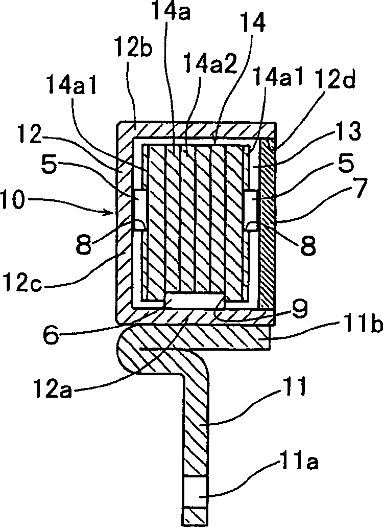
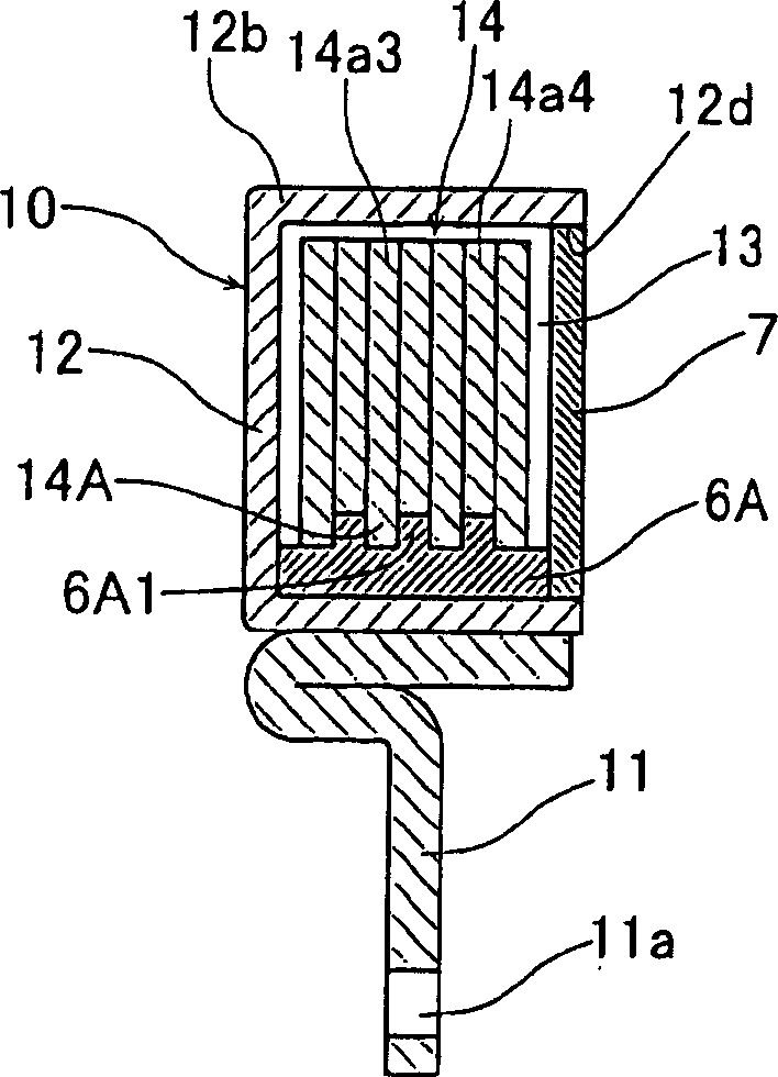
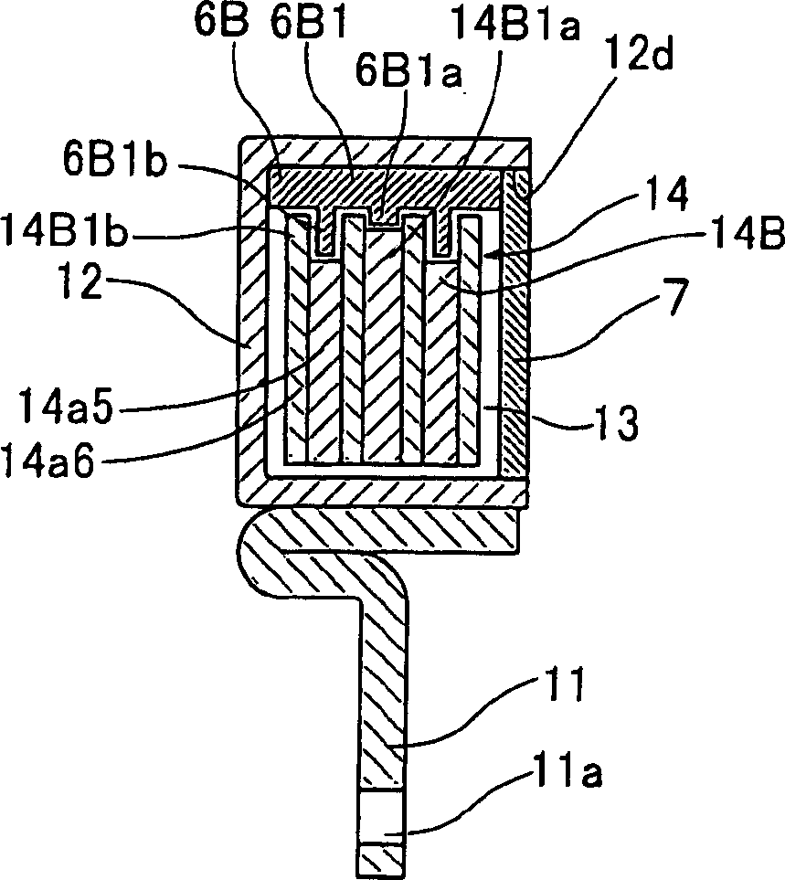
[0031] figure 1 It is a sectional view showing a main part of an embodiment of the viscous damper of the present invention, figure 2 yes means figure 1 A top view of the annular plate portion used by the inertial mass of the damper. In the present embodiment, the viscous damper is composed of the following parts: the casing 10 that liquid-tightly closes the opening 12d of the ring-shaped casing body 12 with a substantially "U"-shaped cross-section and the opening 12d toward one side of the axial direction with the cover 7; An annular inertial mass body 14 housed together in the casing 10 ; and a hub 11 that fixes the casing 10 to a rotating shaft of an internal combustion engine, for example, a crankshaft (not shown) of an automobile engine.

[0032]The hub 11 has an annular fixing part 11b on the outer periphery, which is made of punched sheet material,...


PUM


Abstract

A viscous damper having improved versatility, easy to produce, capable of reducing production cost The viscous damper comprises an annular inertial mass body (14) received in a case (10) together with a damping liquid, and a hub (11) for fixing the case on the rotary shaft of an internal combustion engine. The case comprises a case main body (12) of substantially U-shaped cross section, and a cover (7) for liquid-tightly closing an opening (12d) directed to one axial side of the main body, and defining a sealed chamber (13) in the inside. The inertial mass body is made by superposing and joining a plurality of annular plates (14a). By thrust bearings (5) attached in holes (8) in the annular plate on both axial sides of the inertial mass body and by a journal bearing (6) attached in a recessed groove (9) in the inner periphery of the inertial mass body, the inertial mass body is supported on both axial sides and radially and disposed for peripheral rotation in the sealed chamber (13).

Description

technical field [0001] The present invention relates to a viscous damper mounted on the shaft of an internal combustion engine such as an automobile engine. Background technique [0002] Such as Figure 12 As shown, the viscous damper for absorbing the torsional vibration of the crankshaft of an internal combustion engine is provided with an opening 2a provided on one side of the axial direction of a ring-shaped casing body 2 having a substantially U-shaped cross section in a liquid-tight manner with a cover 7. Shell 3; the ring-shaped inertial mass body 4 accommodated in the shell 3 together with the attenuating fluid (not shown), is fixed on the rotating shaft 1 of the internal combustion engine by bolts through the mounting part 2c integrally formed with the shell body 2. [0003] In the casing 3, the closed chamber 2b is formed by the casing body 2 and the cover 7. The inertial mass body 4 is supported on both sides in the axial direction by the thrust bearing 5, and the...

Claims


Application Information

Patent Timeline
Patent Type & Authority Applications(China)
IPC IPC(8): F02B77/00F16F15/173
CPCY10T74/2121Y10T74/2122Y10T74/2184Y10T74/2183F16F15/173
Inventor 渡边英昭大木和己吉田隆矶野正和
Owner FUKOKU CO LTD
Why Eureka
Try Eureka