
Light reflector

A technology of light reflector and molded body, which is applied in the direction of optics, light guide, electric light source, etc., and can solve problems such as unevenness, lack of rigidity, and bending

Inactive Publication Date: 2005-09-21
YUPO CORP
View PDF5 Cites 12 Cited by
  • Summary
  • Abstract
  • Description
  • Claims
  • Application Information

AI Technical Summary

Problems solved by technology

However, olefin-based thermoplastic resin films are less rigid than polyester films, and may be bent or skewed due to their own easy deformation, and there is a problem in that uniform reflected light is not obtained in the plane direction during use, resulting in uneven brightness.

Method used


Image

  • Light reflector
  • Light reflector
  • Light reflector

Examples


Embodiment

[0154] Examples and comparative examples are described below to more specifically describe the present invention. Materials, usage amounts, ratios, operations, and the like shown below can be appropriately changed without departing from the spirit of the present invention. Therefore, the scope of the present invention is not limited to the specific examples shown below. In addition, the raw materials used in the following examples and comparative examples are shown in Table 1, and the compounding ratio of each raw material when producing the film 1 is shown in Table 2.

[0155] Raw material type

[0156] Mixing ratio of raw materials

[0157] Combination of raw materials

[0158] Combination of raw materials

[0159] Fabrication of Membrane 1

manufacture example 1

[0161] Olefin resin PP1 and HDPE, filler barium sulfate and titanium dioxide were mixed in the ratio recorded in Table 2 to form composition (a), and the composition (a) was melt-kneaded at 250° C. with an extruder; Table 2 Olefin-based resin PP2, filler calcium carbonate 1, and titanium dioxide were mixed at the stated ratio to form a composition (g), and the composition (g) was melt-kneaded at 250° C. with two separate extruders.

[0162] These kneaded products were supplied to a co-extrusion die head set at 250°C, and the composition (a) was used as the middle layer (A) in the die head, and the composition (g) was used as the surface layer (A) on both sides of the die head ( B) and the back layer (C) were laminated, extruded in the form of a film, and cooled to about 60° C. with a cooling roll to obtain a non-stretched laminate (B / A / C).

[0163] After heating the laminate to 145°C, it is stretched to a ratio of 8 times in the longitudinal direction by using the linear speed...

manufacture example 2

[0165] Use different extruders to melt and knead the following compositions at 250°C: the composition (b) formed by mixing olefinic resin PP1 and HDPE, filler barium sulfate and titanium dioxide in the ratio recorded in Table 2; Composition (i) formed by mixing olefinic resin PP2, filler calcium carbonate 2, and titanium dioxide at the ratio described in 2.

[0166] A monoaxially stretched film with a thickness of 100 μm (B / A / C=0.5 μm / 99 μm / 0.5 μm) with a three-layer structure was obtained in the same manner as in Production Example 1, except that the extrusion amounts of these kneaded products were changed. 1.


PUM

PropertyMeasurementUnit
thicknessaaaaaaaaaa
particle sizeaaaaaaaaaa
thicknessaaaaaaaaaa

Abstract

An object of the present invention is to provide a light reflector, which causes no unevenness in luminance in the surface direction due to deflection in use. The present invention is a light reflector comprising: an olefin-based resin film 1 comprising a filler and having a total ray reflectance of 90% or more, which is stretched at least monoaxially at an area stretch ratio of from 1.5 to 80; and at least one of the following substrates (1) to (4): (1) Film 2 comprising at least one of olefin-based resin and polyester-based resin as a main component; (2) Woven cloth 3 or non-woven cloth 4; (3) Metal plate 5; and (4) Molded material 6 comprising a thermoplastic resin composition (a1) containing a foaming agent and having a foaming ratio of from 1.05 to 10 as calculated by the following equation (1): <DF NUM="(1)">Foaming ratio = rho o / rho < / DF> where po represents the density before foaming; and rho represents the density after foaming.

Description

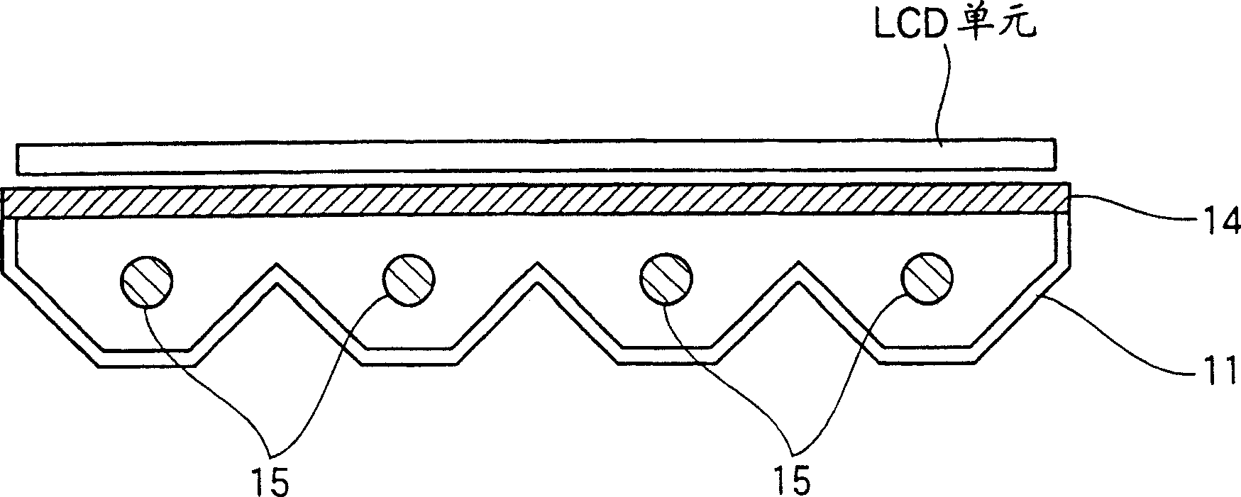
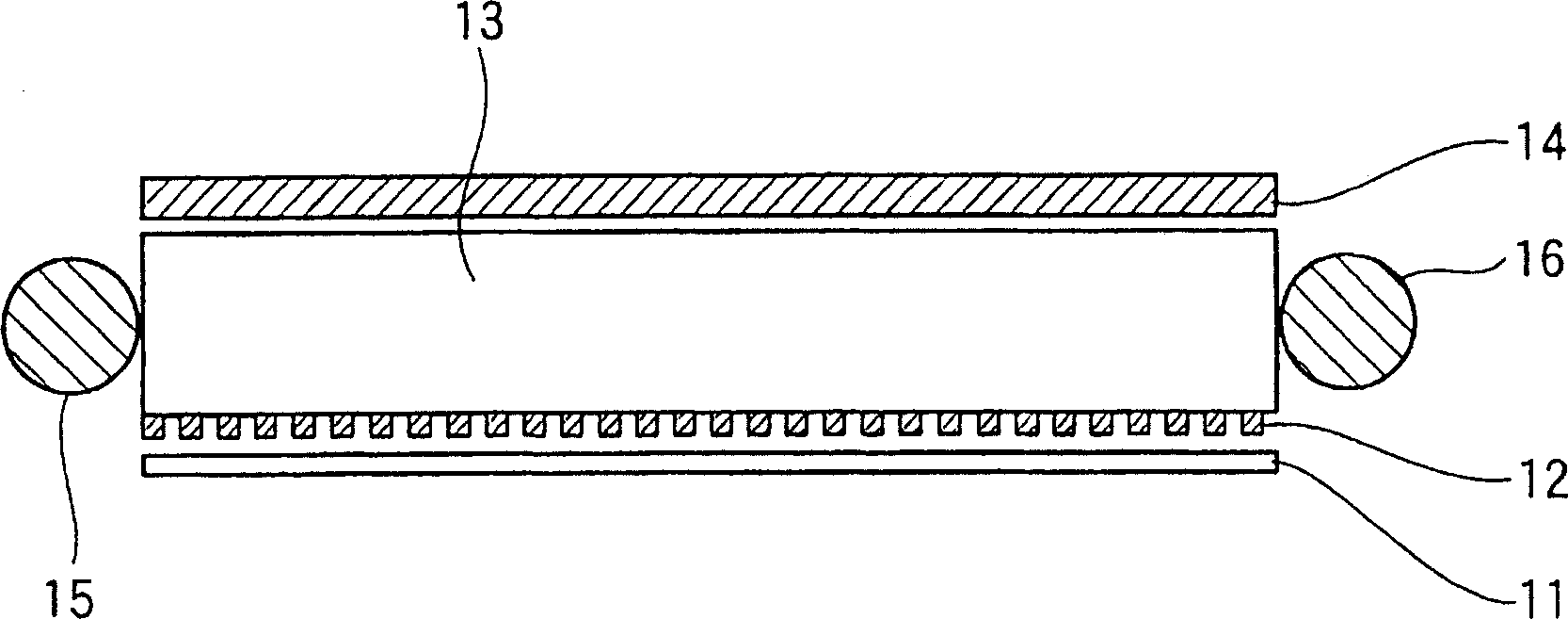
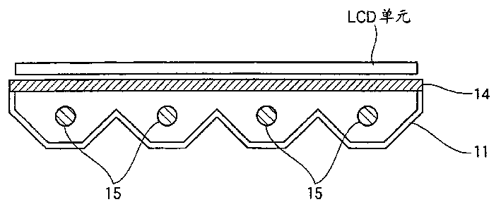
technical field [0001] The present invention relates to light reflectors. Specifically, it relates to a reflector that reflects light from a light source such as a fluorescent lamp in a backlight type surface light source device that tends to be larger in size, and also relates to a reflector that does not cause brightness unevenness in the surface direction due to softness when used because it has sufficient rigidity. light reflector. Background technique [0002] In recent years, backlight-type liquid crystal displays and printed matter lighting panels in which built-in light sources are arranged have spread widely. In the built-in surface light source device of the backlight type (hereinafter referred to as the backlight unit), the typical structure of the side light method is as follows: figure 2 As shown, it consists of a light guide plate 13 on which halftone printing 12 has been applied to a transparent acrylic plate, a light reflector 11 disposed on one side thereo...

Claims


Application Information

Patent Timeline
Patent Type & Authority Applications(China)
IPC IPC(8): B32B1/00B32B27/00G02B1/10G02B5/08
CPCB32B27/00G02B5/0841B32B1/00G02B5/0808Y10T428/24355B32B15/085B32B5/024B32B5/022B32B27/365B32B27/32B32B27/20B32B7/12B32B27/12B32B27/08
Inventor 高桥友嗣上田隆彦小山广大川内一郎
Owner YUPO CORP
Learn More