AC LED lighting lamp
A technology for LED lighting and LED filament, which is applied in lighting devices, lighting and heating equipment, and lamp circuit layout, etc., can solve the problems of high-cost popularization and promotion of switching circuits, difficulty in balancing current density, and high cost of driving circuits, and achieves a high cost. Conducive to flexible application, avoiding low life and easy decay, simplifying process and design
- Summary
- Abstract
- Description
- Claims
- Application Information
AI Technical Summary
Problems solved by technology
Method used
Image
Examples
Embodiment 1
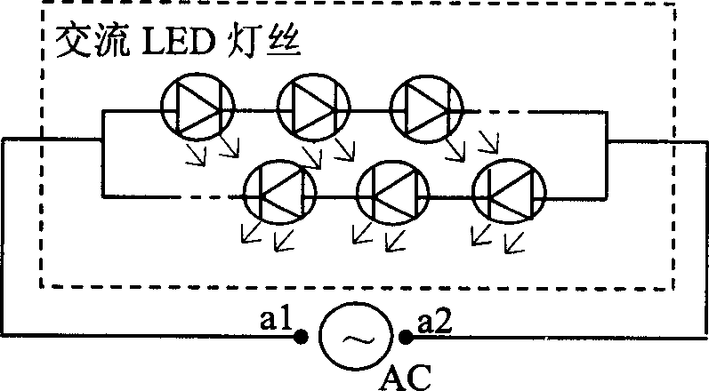
[0024] Embodiment 1. A single-filament AC LED lighting lamp, combined with figure 1 , including AC input terminals a1, a2 and AC LED filaments connected between the AC input terminals, the AC LED filaments include two parallel rows of light-emitting diode columns with opposite conduction directions, and each column of light-emitting diode columns is composed of several light-emitting diode columns Diodes are connected in series. The AC input terminals a1 and a2 are directly connected to the AC power supply AC.
[0025] The specific number N of series-connected LEDs in each LED column can be determined according to the required operating voltage ACV in the following manner,
[0026] N=Int(DCV / Vf)
[0027] Among them, Int means rounding the result, Vf is the nominal voltage value of the light-emitting diode, which is generally 1.8-2.2V for yellow and red light-emitting diodes, and 3.0-3.4V for green and white light-emitting diodes.
[0028] DCV = ...
Embodiment 2
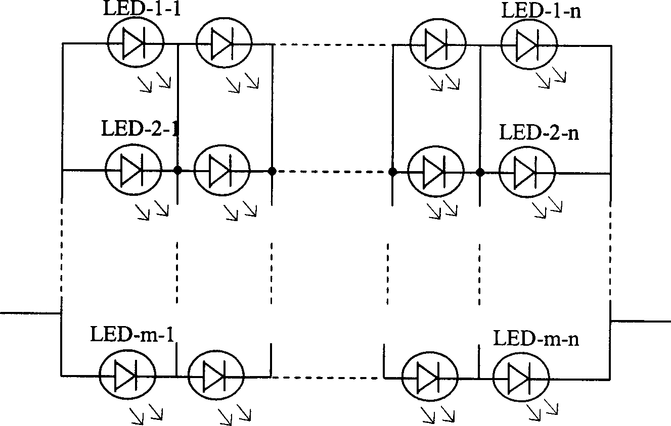
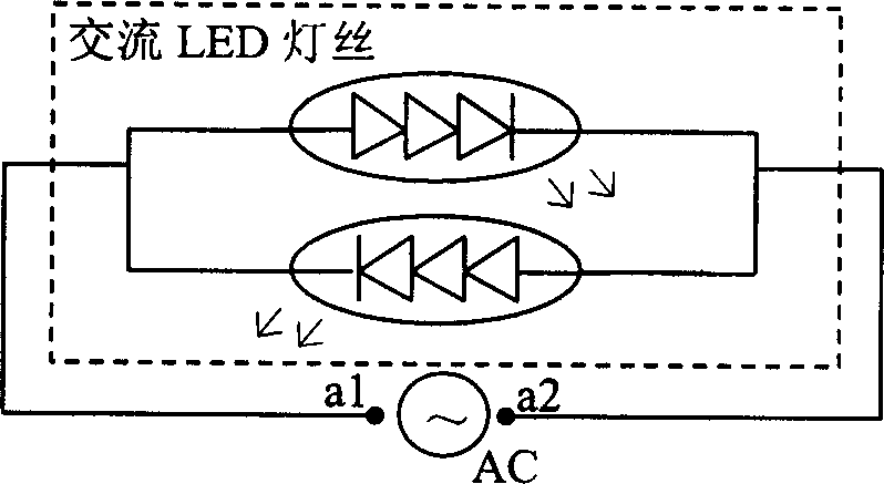
[0031] Embodiment 2. An integrated single-filament AC LED lighting lamp, combined with image 3 and Figure 4 , including the AC input terminals a1, a2 and the AC LED filament connected between the AC input terminals. The AC LED filament in this example adopts a three-level integrated AC LED filament. The structure diagram is shown in Figure 4 , including two columns of series-connected integrated dies with opposite conduction directions, each column of series-connected integrated dies consists of three light-emitting diode dies 2, 3, 4 components, each single die becomes the first level of the series integrated die, a is the positive pole of the single die, b is the negative pole, and c is the luminous body part. The positive pole of the die 4 and the negative pole of the die 2 are electrically connected to the positive pole A and the negative pole B of the substrate, respectively.
[0032] According to the structure in this embodiment, each column of series-connected inte...
Embodiment 3
[0037] Embodiment 3, a multi-terminal control multi-filament AC LED lighting lamp, combined with Figure 8 , including AC input terminals a1, a2 and three AC LED filaments composed of red R, green G, and blue B LEDs respectively, and the three filaments are respectively connected to the AC input terminals through thyristor control switches. The structure of each single die is the same as that in the first embodiment.
[0038] In actual use, the color and brightness of the entire LED lighting can be adjusted by controlling the thyristor control terminals Rc, Gc, and Bc of the three filaments R, G, and B.
[0039] In addition to using red, green, and blue as the combination of filament colors, yellow and blue combinations can also be used. Of course, the same single-color filament can also be used. In this case, the control switch controls the overall brightness of the lamp. In addition, in addition to using thyristors as filament control switches, in some large-scale LED array...
PUM
 Abstract
Description
Claims
Application Information
 - R&D
- Intellectual Property
- Life Sciences
- Materials
- Tech Scout
- Unparalleled Data Quality
- Higher Quality Content
- 60% Fewer Hallucinations
Browse by: Latest US Patents, China's latest patents, Technical Efficacy Thesaurus, Application Domain, Technology Topic, Popular Technical Reports.
© 2025 PatSnap. All rights reserved.Legal|Privacy policy|Modern Slavery Act Transparency Statement|Sitemap|About US| Contact US: help@patsnap.com


